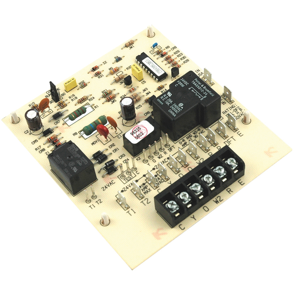
Oem upgraded rheem heat pump defrost control circuit board sensor 47 21517 22 48 out of 5 stars 23. Electronic timer and defrost cycle start only when contactor is energized and defrost thermostat dft is closed below 36 f 22 c.

Wrg 1178 Goodman Heat Wiring Diagram
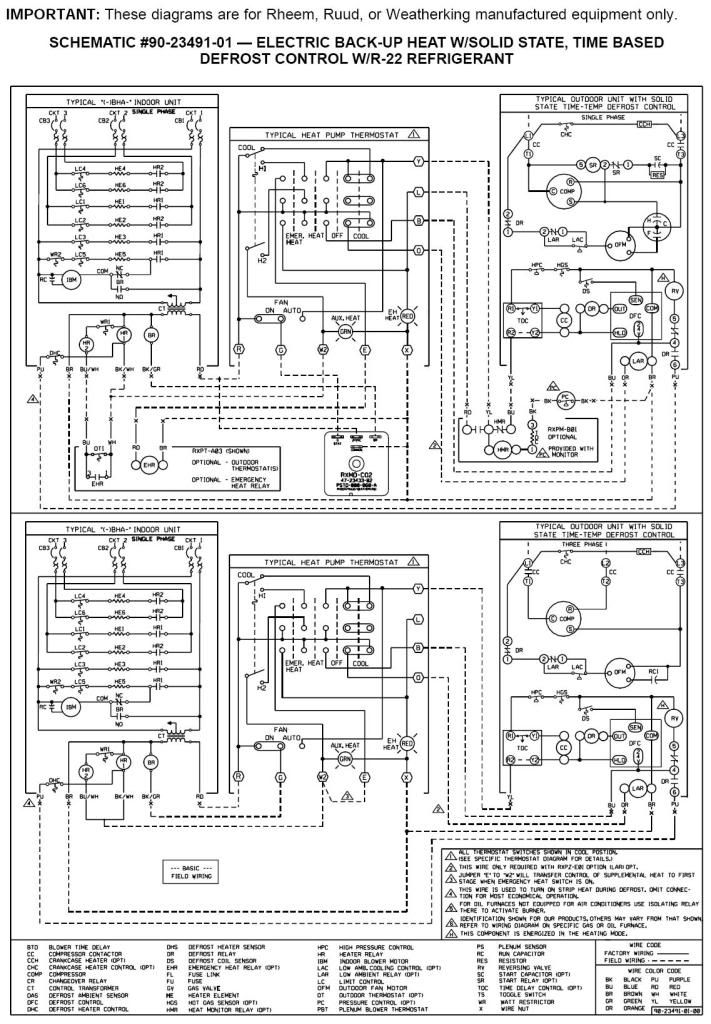
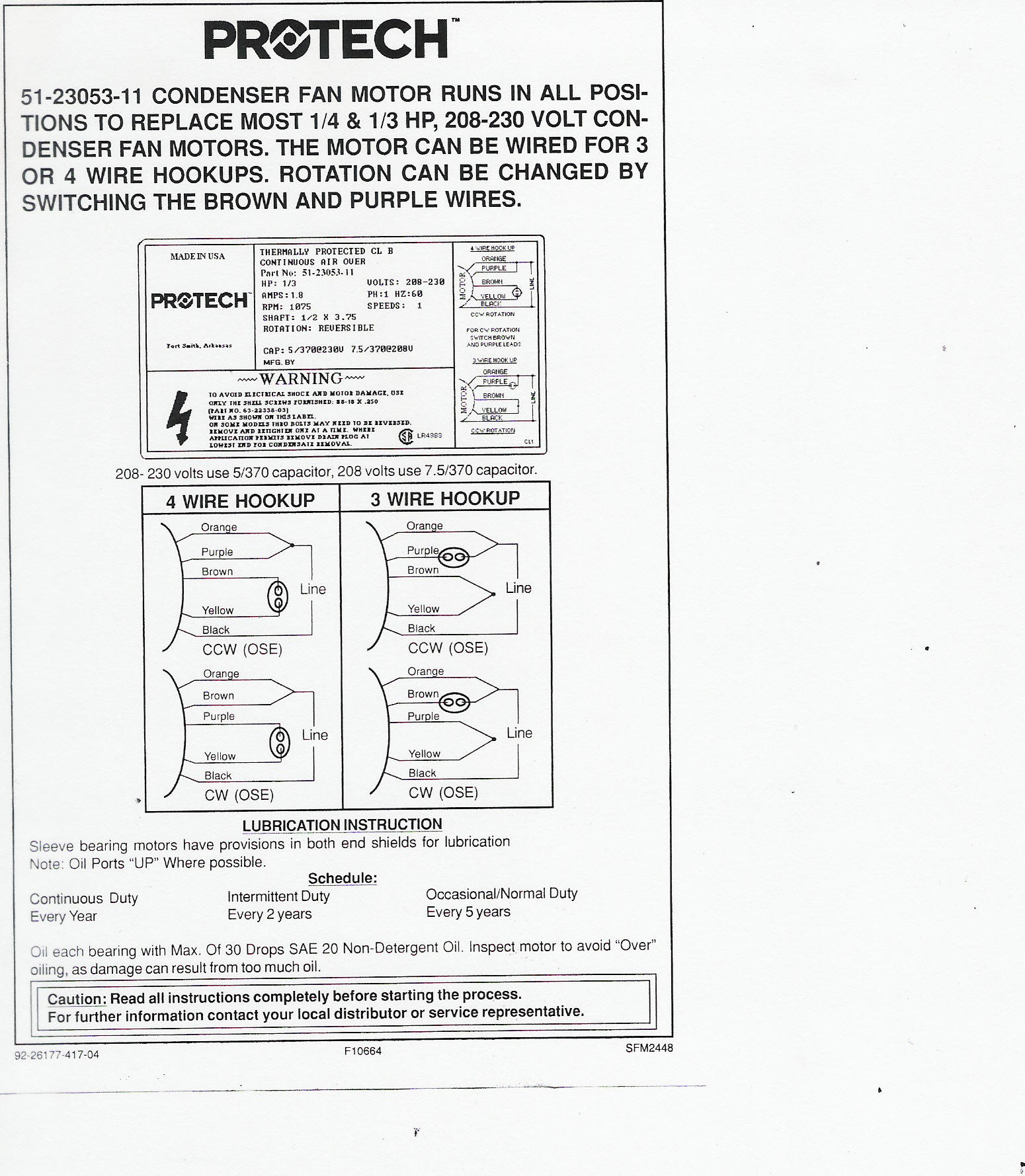
Rheem defrost board wiring diagram. R 410a refrigerant package heat pumps 2 5 tons. Variety of ruud heat pump thermostat wiring diagram. Rqmp 14 series heat pump pdf manual download. It shows the elements of the circuit as streamlined forms and the power as well as. It reveals the elements of the circuit as simplified shapes as well as the power as well as signal connections between the gadgets. View and download rheem rqmp 14 series installation instructions manual online.
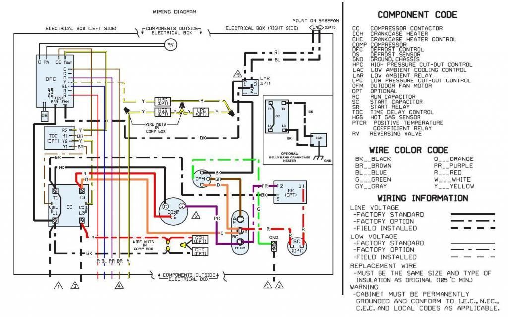
Rheem heat pump wiring diagram download. A wiring diagram is a streamlined conventional photographic representation of an electrical circuit. Rheem wiring diagram cinema paradiso. It reveals the parts of the circuit as simplified shapes and the power and signal links between the devices. Collection of rheem heat pump wiring diagram. Defrost control indicates a call for unit operation is present at the heat pumpdefrost control.
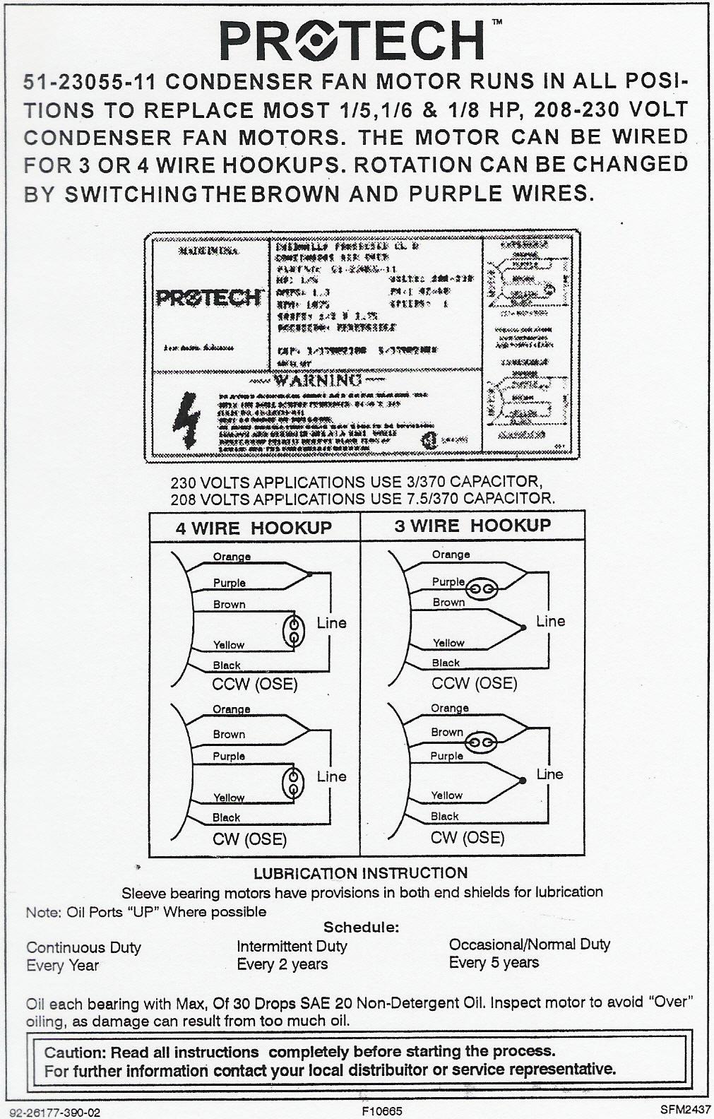
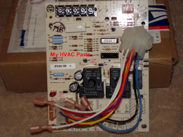
The 47 102684 83 heat pump defrost control is used on many rheem ruud heat pumps. Rqnm 13 series rqmp a024jk rqmp a030jk rqmp a036ck rqmp a036jk rqmp a042ck rqmp a042jk. Assortment of rheem air handler wiring schematic. Protech 47 102685 87 defrost control board 45 out of 5 stars 25. How to know if your heat pump defrost board is working properly so that it wont freeze up. A wiring diagram is a streamlined standard photographic depiction of an electrical circuit.
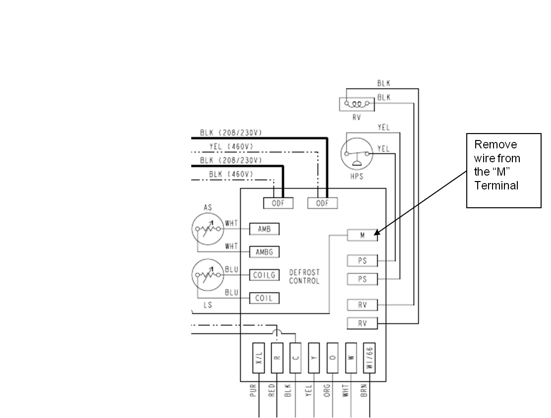
According to the instructions there is a control wire that runs from d on the heat pump to p on the air handlers control board. My rheem heat pump has a defrost cycle. Supervision is needed by a licensed hvac tech before doing this as experience and apprenticeship garners. Defrost the defrost board db is a time and tempera ture control which includes a field selectable time period between checks for frost 30 50 and 90 minutes. A wiring diagram is a streamlined traditional photographic representation of an electrical circuit. The heat pumpdefrost control will attempt to start unit after the anti short cycle time expires when a high or low pressure control automatically resets or when the heat pumpdefrost control exits the lockout mode as the temperature rises above 5f.
I find no p terminal on the air handler to connect. The 47 102684 83 rheem ruud heat pump defrost control board is brand new and comes in an anti stat bag packed in a genuine oem protech factory parts box. So we either freeze every winter while the unit is going thru its defrost cycle or we have to activate the emergency heat. Brand new oem upgraded heat pump defrost control control board upgrade kit comes with wiring instructions and all hardware you may or not need to update your board.
Gallery of Rheem Defrost Board Wiring Diagram