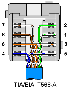
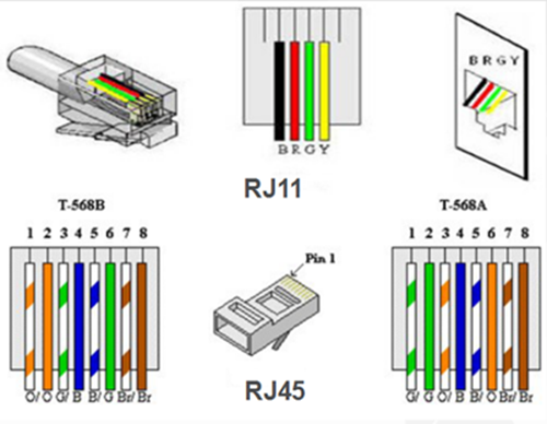
That plug is inserted into rj45 jacks of ethernet devices. The jack should have a wiring diagram or designated pin numberscolors to match up to the color code below.

Rj45 Pinout Diagram Networkel
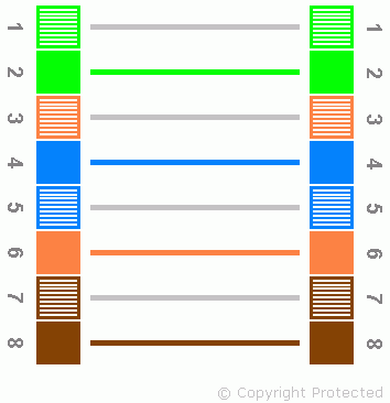
Rj45 connection diagram. Repeat the above steps for the second rj45 plug. The cable is called wipe patch cord straight thru cable. Once a socket has been wired to each end of the network cable the final connection can be made using patch leads. The complete ethernet pinout cable wiring reference with wiring step by step guide. Rj45 registered jack 45 is the connector that consists of 8 metal connection point. The term plug refers to the cable or male end of the connection while the term jack refers to the port or female end.
This article shows how to wire an ethernet jack rj45 wiring diagram for a home network with color code cable instructions and photosand the difference between each type of cabling crossover straight through ethernet is a computer network technology standard for lan local area network. Rj45 exists at the end of the ethernet cables that is used for internetwork communication. Each component should be set and connected with different parts in particular way. Rj45 pinout diagram shows the way how that connector provides communication with network devices. If you want to crimp an rj45 connector to the end of the cable you can watch. The wiring diagram is shown with the hook clip on the underside.
Cut the ethernet cable to length make sure it is more than long enough for your needs. Rj45 connectors are commonly seen with ethernet cables and networks. The wall jack may be wired in a different sequence because the wires may be crossed inside the jack. Pinout of ethernet 10 100 1000 mbit cat 5 cat 5e and cat 6 network cable wiringnowdays ethernet is a most common networking standard for lan local area network communication. It reveals the components of the circuit as simplified shapes and the power as well as signal connections in between the devices. Remember the rj45 wiring order.
Verify the wires ended up the right order and that the wires extend to the front of the rj45 plug and make good contact with the metal contacts in the rj45 plug. The ethernet cable used to wire a rj45 connector of network interface card to a hub switch or network outlet. Crimp the rj45 plug with the crimper tool. Click to check the right one for you or print as reference. It was introduced commercially in 1989 and became ieee standard 8023 in 1983. Collection of cat 6 wiring diagram rj45.
If not the arrangement will not function as it ought to be. The t 568b standard is the most commonly used. Modern ethernet cables feature a small plastic plug on each end of the cable. Rj45 pinout diagram shows wiring for standard t568b t568a and crossover cable. A wiring diagram is a streamlined standard photographic depiction of an electric circuit. Rj45 wall socket wiring diagram cat5e wall plug wiring diagram cat5e wall socket wiring diagram clipsal rj45 wall plate wiring diagram every electrical structure consists of various different parts.
Click to find view print and more.


