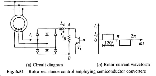
The ac output voltage of the rotor is rectified by diode bridge rectifier and fed to parallel combination of fixed resistor r and a semiconductor switching transistor t reffective value of resistance across terminal a and b ie r ab is varied by varying duty cycle of the transistor t r which in turn. But the maximum torque remains constant.
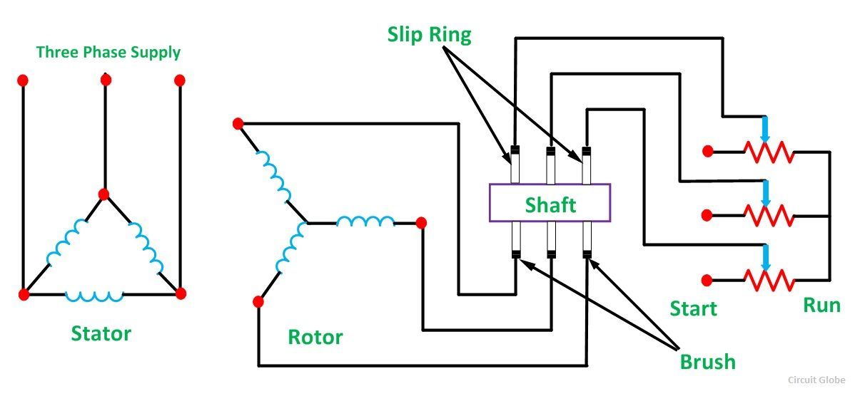
What Is A Slip Ring Induction Motor Quora
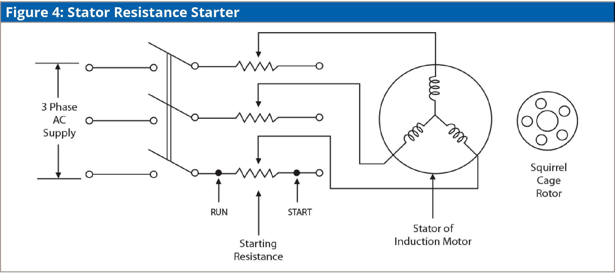
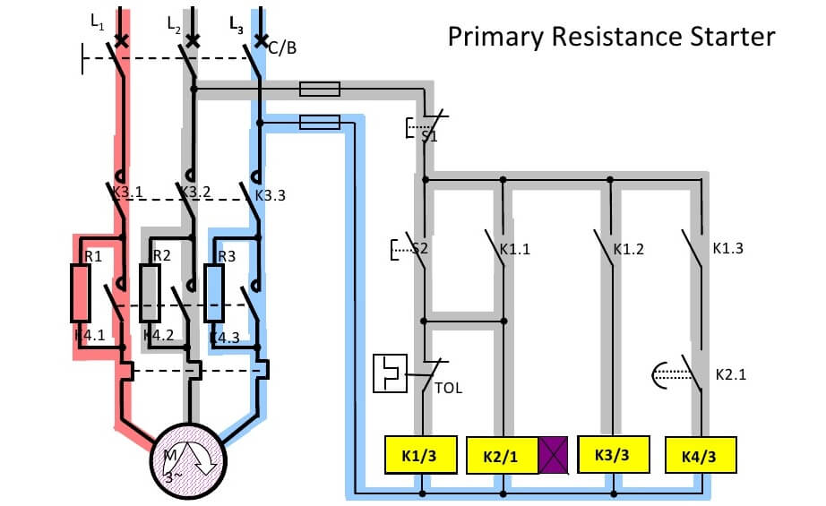
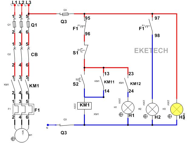
Rotor resistance starter control circuit diagram. It is possible to have a large starting torque low. This means increasing rotor resistance results in increase in slip. The rotor circuit resistance has significant impact on starting torque the speed at which the breakdown torque occurs and the slip during the normal running operation. Lecture 36rotor resistance speed controlrotor side speed control3 phase induction motor duration. Introducing resistance in rotor current will decrease the starting current in the rotorand hence in. Only for you 68569 views.
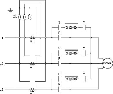
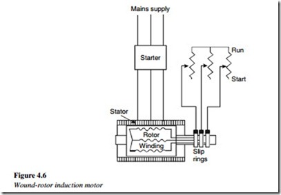
These motors are started with full line voltage as external resistance can be easily added to the rotor circuit with help of slip ringsa star connected rheostat is connected in series with the rotor via slip rings. Thus we can say that by rotor resistance control we can achieve variable speed at a constant torque. When the power is high electrodes are driven by a small motor. Increase in slip in turn means reduction in induction motor speed. Three phase slip ring rotor starter control power diagrams 3 phase slip ring rotor starter control power diagrams slip ring rotor power and control breaking news up tp 93 off launching official electrical technology store shop now. Rotor resistance can also be varied steplessly using circuit of fig.
Electrical yatra 6591 views. Advantage of this method is that resistance can be changed steplessly. Thus by rotor resistance control method the speed control is provided by the rated speed to the lower speedsthis method of speed control is very simple. If the resistance of the motor is increased then the pull out speed of the motor decreases. Speed control of induction motor part 1. Static rotor resistance control.
714 shows how the motor torque speed curve would change if rotor resistance is increased and all other parameters in the motor equivalent circuit stay the same. In the above figure the maximum torque is same for rotor resistance r 1 r 2 and r 3 but the slip increase from point a to b c. Resistance is varied by changing the distance between electrodes and earth electrode. Rotor resistance can also be varied steplessly using the circuit shown in figure a. Rotor resistance starter in three phase induction motor. Overhead crane or eot crane power diagram duration.
Gallery of Rotor Resistance Starter Control Circuit Diagram