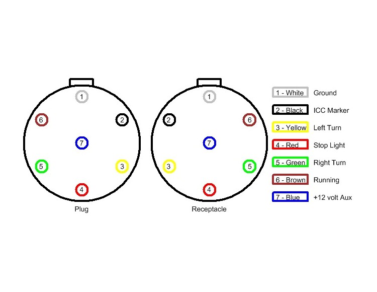
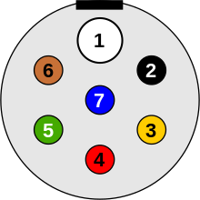
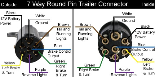
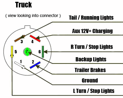
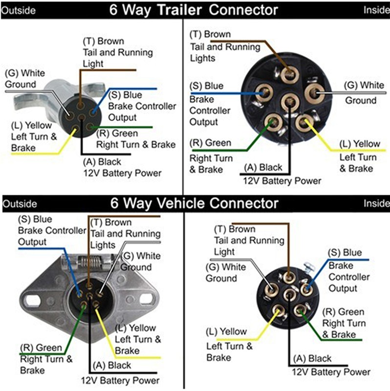
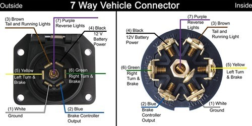
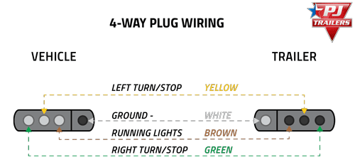
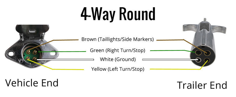
They also provide a wire for a ground connection. Below is the generic schematic of how the wiring goes.
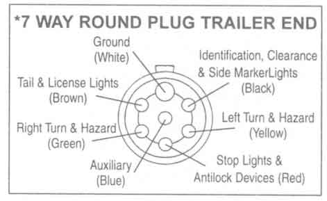
7 Round Plug Wiring Diagram H1 Wiring Diagram
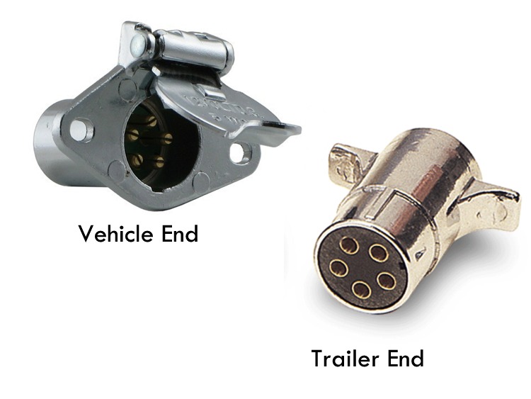
Round trailer light plug wiring diagram. Round 1 14 diameter metal connector allows 1 or 2 additional wiring and lighting functions such as back up lights auxiliary 12v power or electric brakes. Check with a test light or vom. Also it must connect with things if included that use the aux power and back up lights too. 4 pin trailer wiring diagram. The black sometimes red 12v and blue electric brakes wire may need to be reversed to suit the trailer. A wiring diagram is a simplified standard pictorial depiction of an electric circuit.
Some trailer builders just connect this wire to the frame then connect the ground from all the other lights and accessories to the frame as well. As the name implies they use four wires to carry out the vital lighting functions. Note that this type of 4 pin connector is less common that 4 pin flat connector. 6 way systems round plug. Variety of 7 pin round trailer wiring diagram. Above we have describes the main types of trailer wiring diagrams.
The trailer wiring diagram shows this wire going to all the lights and brakes. If custom wiring is not available for your particular make and model a taillight converter may be required to equip your vehicle with the proper trailer light wiring connection. This type of connector is normally found on utvs atvs and trailers that do not have their own braking system. It reveals the parts of the circuit as simplified forms as well as the power and also signal links between the tools. The four wires control the turn signals brake lights and taillights or running lights. 4 way trailer connectors are.
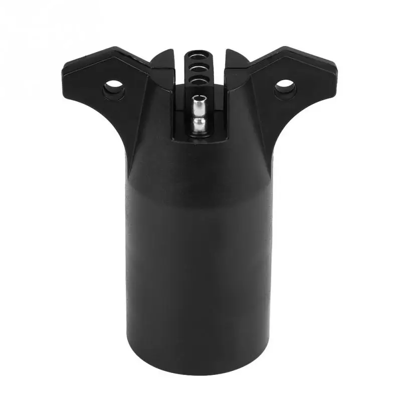
4 way trailer connectors are typically used on small trailers such as boat snowmobile utility and other trailers that that do not use brakes. A taillight converter or electrical converter splices into your vehicle and provides a standard trailer plug wiring connector typically a 4 way flat.
