Thermostat it is imperative that the programmer knows the types of appliances that have been installed in the motor coach in each zone. 12vdc 6 part number.

How To Change Your Rv Thermostat Part 1 Of 6 Youtube
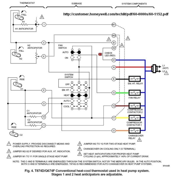
Rv comfort hp thermostat wiring diagram. Figure 18 thermostat wiring diagram e option. When the coil is activated an electromagnet inside the relay will pull the contacts closed. 24 hp or conventional auto or manual changeover. Typically the connections are made as follows. Terminal 03 is usually hot taking a red wire from the rvs 12 volt coach system. This system can control up to four zones in a motor coach.
Rv products suggests the thermostat wiring be a minimum of 18 gauge. Insert the stripped harness wires into the thermostat terminals according to your wiring diagram. Terminal 01 is usually ground taking a black or blue wire to the campers 12 volt neutral system. The 8530a345 8530 338 8530 346. A zone is an area of a motor coach that is climate controlled. Look for and.
Fuse the thermostat is equipped with a replaceable fast acting 2 amp fuse located on the base of the thermostat. 12vdc travels from the thermostat red wire to the thermostat yellow y wire and then to the relay coil. Thermostat wire connection function of low voltage terminal extending from ceiling plenum r red provides 12 vdc to upper unit control box cool shed 2 terminals white jumper wire removing jumper wire will allow system to be connected to nc. The 8530a345 8530 346 thermostat are intended for use with an rv must supply the 12 vdc wiring and the furnace control wiring. The only difference is the color of the thermostat. 8530 348 and 8530 349 thermostat are intended for use with an rv products rooftop heat pump.
The furnace control circuit must not exceed 1 amp. Operation all 9330 33 thermostats function identically. This thermostat will work with any rv products air conditioner that is controlled with an rv products zone control box. Rv products suggests the thermostat wiring be a minimum of 18 gauge. G1 bk yo rv. Figure 17 thermostat wiring diagram x option.
Thermostat for use on rooftop hp with fresh air intake and gas furnace power. The oem original equipment manufacturer must supply the 12 vdc wiring and the furnace control wiring. The heating appliance control circuit must not exceed 1 amp. Contacts of a load shed system heat shed 2 terminals white jumper wire removing jumper wire will. The 115vac will now operate the compressor until the thermostat opens or the system switch is turned to the off position. Four versions of the comfort series line of thermostats.
1 stage cool 2 stage heat digital wall thermostat for use with 1 stage ac and 2 stage gas furnace power. The thermostat is equipped with a.


