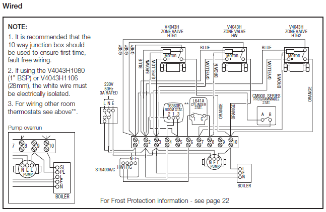
The splice tube contains a. A wiring diagram is a streamlined conventional photographic depiction of an electrical circuit.

Ew 8266 Wiring Diagram For Float Switches Free Diagram
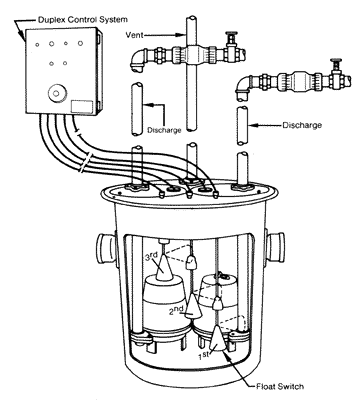
Septic pump float switch wiring diagram. If your septic system uses a pump to remove wastewater from the tank to a drain field your system will include a septic tank alarm and float switch. Each part ought to be set and connected with different parts in particular manner. Assortment of septic pump float switch wiring diagram. We recommend using a. Septic pump float switch wiring diagram what is a wiring diagram. When the float rises to an unacceptable level it sets off an alarm to warn you that your tank may be about to overflow.
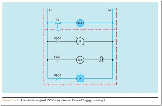
It reveals the components of the circuit as streamlined shapes as well as the power as well as signal links in between the tools. If not the arrangement will not work as it ought to be. It shows what sort of electrical wires are interconnected and may also show where fixtures and components may be connected to the. A wiring diagram is an easy visual representation of the physical connections and physical layout associated with an electrical system or circuit. When the liquid level gets too high a switch inside the float closes the alarm circuit activating the alarm. Septic tank float switch wiring diagram septic tank 3 float switch wiring diagram septic tank float switch wiring diagram every electrical arrangement is made up of various diverse components.
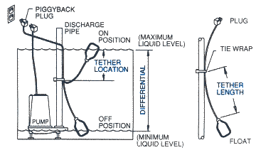
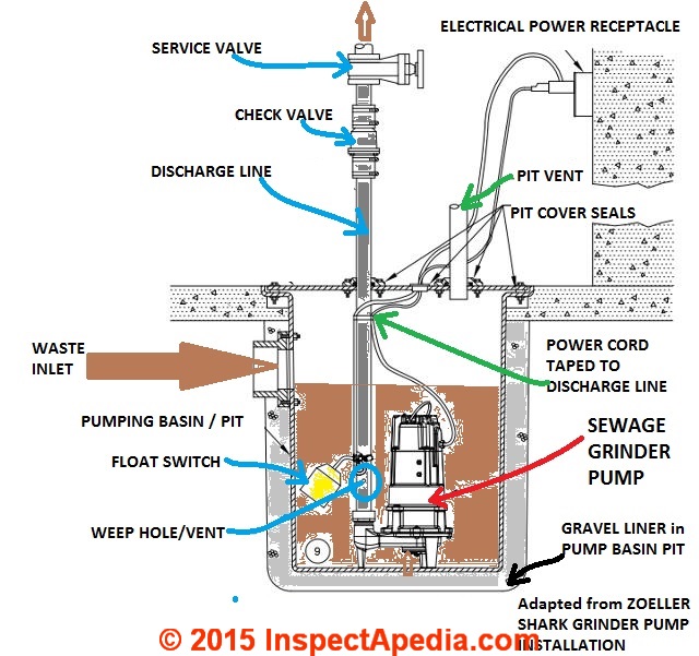
The float switch moves with the water level in the tank and this determines when the pump turns on and shuts off. The double float pump switch consists of two floats and a splice tube. Detailed step by step video of how to wire a septic pump and alarm system. In this article we will discuss the correct way to hard wire a float switch to a submersible pump in order to achieve automatic operation. At times the float switch will malfunction and sound the alarm when the. Inside the septic tank a float switch tethered to a fixed position in the tank floats up and down with the liquid level.
As far as i am aware this is fully adequate to satisfy nec codes. The information below refers to 115v pumps and wiring. Always observe local codes that may differ. Chris shows you how to correctly wire the double float pump switches made by sje rhombus. It shows the parts of the circuit as simplified forms and also the power and also signal links between the devices. A wiring diagram is a streamlined traditional pictorial depiction of an electrical circuit.
Septic system alarms alert the homeowner when an imminent sewage back up is likely. Variety of septic tank float switch wiring diagram.


