A servo is a small device that has an output shaft. Again the controller must know the exact position of the rotor using encoder for precise speed and position control.

Dc Servo Motors Stepper Motor
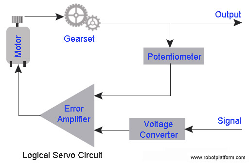
Servo motor diagram. This is the simple basic design of servo motor controller with pulse generator. There are lots of servo motors available in the market and each one has its own speciality and applications. The following two paragraphs will help you identify the right type of servo motor for your projectsystem. The servo motor has some control circuits and a potentiometer a variable resistor aka pot connected to the output shaft. The rotor of the motor has the long length and smaller diameter. They operate at very low speed and sometimes even at the zero speedthe servo motor is widely used in radar and computers robot machine tool tracking and guidance systems processing controlling etc.
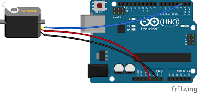
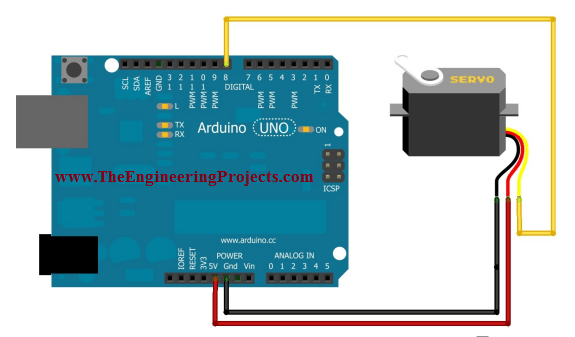
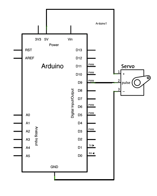
Selecting your servo motor. The working principle of this servo motor is similar to the normal induction motor. It uses the cmos ic 7555 in the astable mode to generate pulses to drive the servo motor. This pot allows the control circuitry to monitor the current angle of the servo motor. Every servo motors will have three terminals one for positive supply another for ground supply and other one for position control signal input. Working of a servo motor.
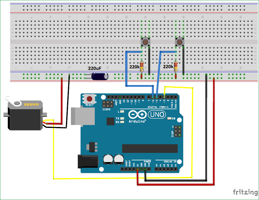
This circuit is designed to give pwm pulse width modulation signal output by using this different duty cycle pwm pulse we can control the servo motor. In the picture above the pot can be seen on the right side of the circuit board. The circuit can be suitably modified to get pulses of sufficient length. The rotor inertia of the motors is low and have a high speed of response. Working principle of ac servo motor. Mg90s metal gear mg995 high torque metal gear vts 08a analog servo.
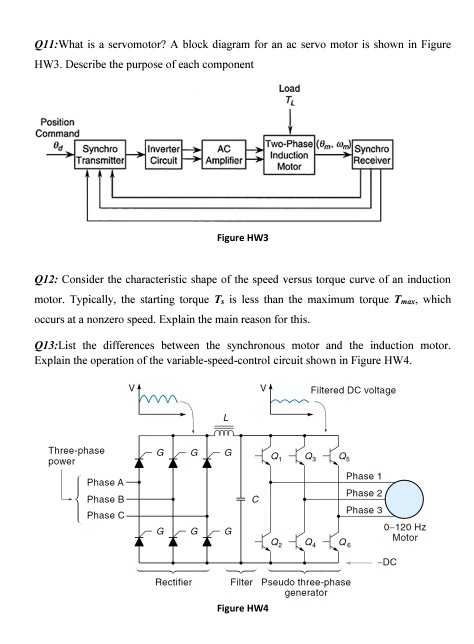
Sg 90 servo motor equivalent. The schematic diagram of servo system for ac two phase induction motor is shown in the figure below.

