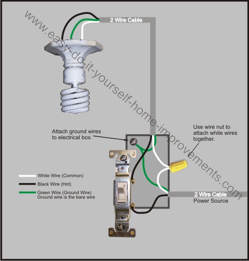
Standard single pole switches do not connect to neutral circuit wire. With a pair of 3 way switches either can make or break the connection that completes the circuit to the light.
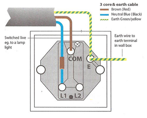
Single Light Switch Wiring Diagram Uk H1 Wiring Diagram
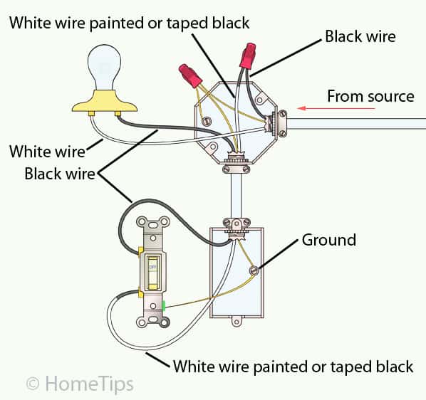
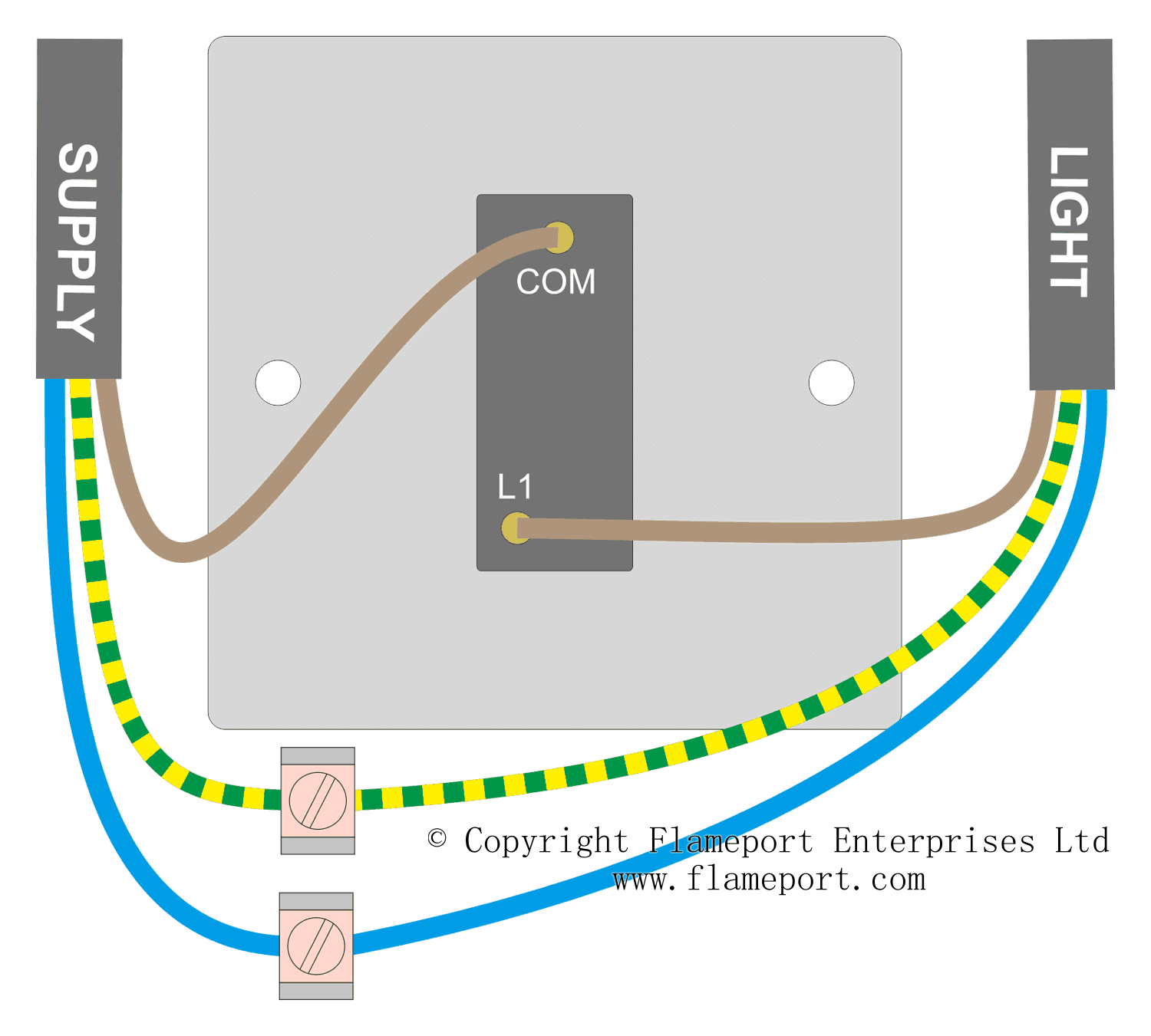
Single light switch wiring diagram. Light switch wiring diagram single pole this light switch wiring diagram page will help you to master one of the most basic do it yourself projects around your house. Wiring a single pole light switch. The other terminal is for a second hot wire called a switch leg that runs only between the switch and the light fixture. Wiring a 3 way light switch. Multiple light wiring diagram. Single pole switch wiring diagram 2 single pole switching provides switching from one location only.
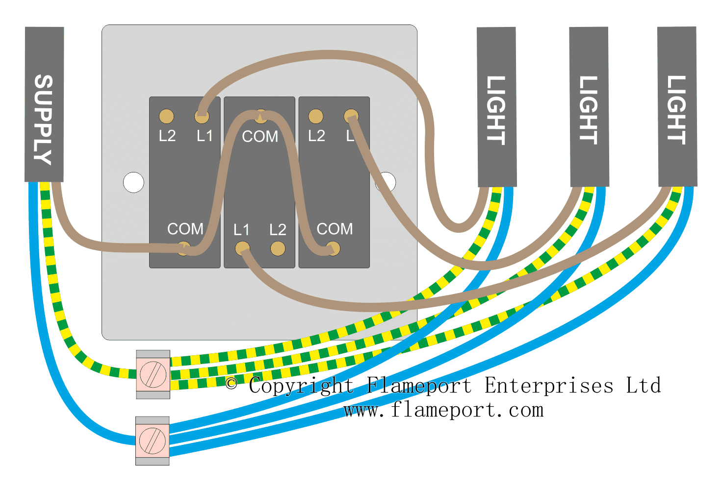
I have an existing light switch and i want to add a second switch for a new light that will be operated separately. Single pole switch diagram 2 this switch wiring diagram shows the power source starting at the fixture box. From this post you complete learn about light switch wiring with a simple diagram and video tutorial in english language. How is the wiring for a new light switch and fixture added to an existing switch. This diagram illustrates wiring for one switch to control 2 or more lights. This light switch wiring diagram shows the power source starting at the switch box.
The wiring of light switch is very simple connection but before we start the wiring connection. The power comes into the switch which operates a single light at the end of the circuit. The hot and neutral terminals on each fixture are spliced with a pigtail to the circuit wires which then continue on to the next light. The ground screw is for the circuit ground wire connection. And this will be complete guide of wiring a light switch. A dimmer switch is wired the same way as a single pole switch.
Light switch wiring diagram. Wiring a 3 way light switch is certainly more complicated than that of the more common single pole switch but you can figure it out if you follow our 3 way switch wiring diagram. In this illustration you can see the red hot lead wires of the dimmer are connected to the inbound black wire from the electrical source the electrical panel and the black wire that goes to the light fixtures black wire which in this case is a white wire that has been taped with black electrical tape. The switch leg brings power to the fixture when the switch is turned on. The source is at sw1 and 2 wire cable runs from there to the fixtures.


