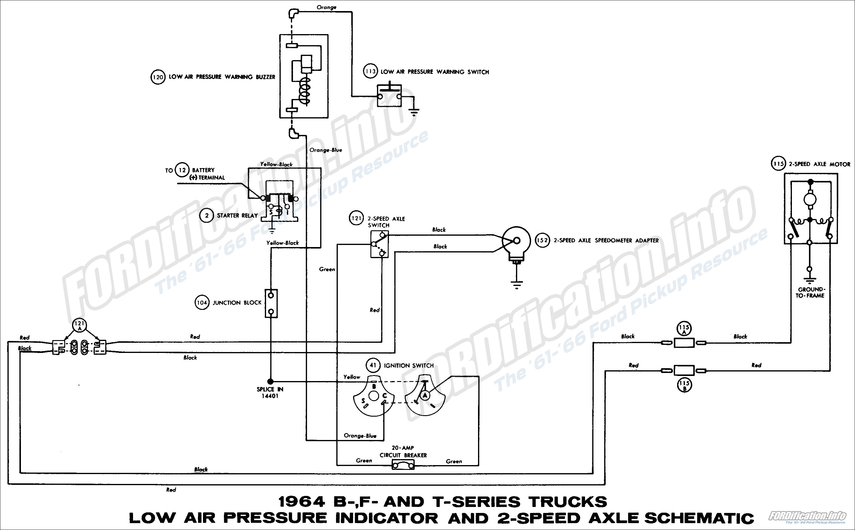
Like subscribe and dont skip the ads. One contactor burnt for high speed and a replced contactor does not engange originally the coils re fed with a nutural and the one i replaced is only working with a phase.

Practical Machinist Largest Manufacturing Technology Forum
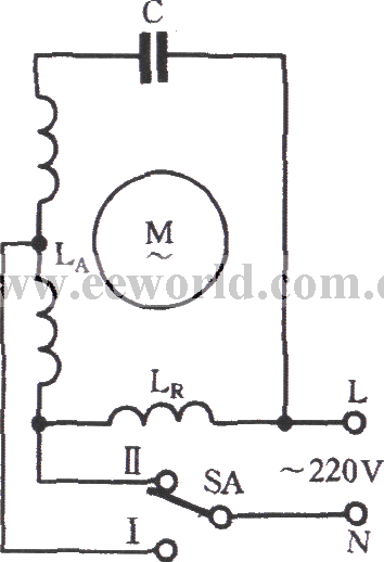
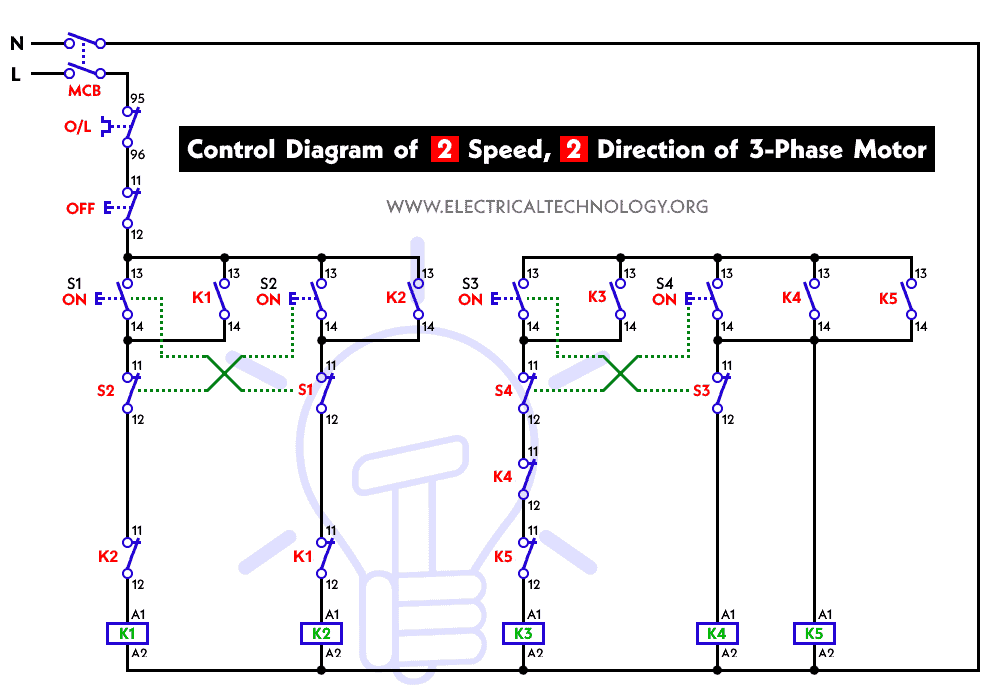
Single phase 2 speed motor wiring diagram. Power and control circuit for 3 phase two speed motor. Please help how to go about this. Click here to view a capacitor start motor circuit diagram for starting a single phase motor. Also read about the speed torque characteristics of these motors along with its different types. Diagram dd5 two speed motors for all other single phase wiring diagrams refer to the manufacturers data on the motor. Kindly email me the diagrams for star deltor and direct online for a 3speed 1directon 3ph motor have two of them in a bow cutter.
Wondering how a capacitor can be used to start a single phase motor. For specific leeson motor connections go to their website and input the leeson catalog in the review box you will find connection data dimensions name plate data etc. Three phase see below single voltage. Diagram dd5 two speed motors for all other single phase wiring diagrams refer to the manufacturers data on the motor. Learn how a capacitor start induction run motor is capable of producing twice as much torque of a split phase motor. The load will slow the motor down.
Electric motor wire marking connections. A split phase capacitor start electric motor may be defined as a form of split phase motor having a capacitor connected in series with the auxiliary winding. The auxiliary circuit is opened by the centrifugal switch when the motor reaches 70 to 80 percent of synchronous speed. Thermal contacts tb white m 1 z2 yellow z1 blue u2 black u1 red bridge l1 and l2 if speed controller sc is not required m 1 ln e. Single phase 2 speed motor wiring diagram wiring diagram is a simplified pleasing pictorial representation of an electrical circuitit shows the components of the circuit as simplified shapes and the facility and signal connections together with the devices. One more thing to keep in mind is that the actual operating speed for a motor like this is determined by the load.
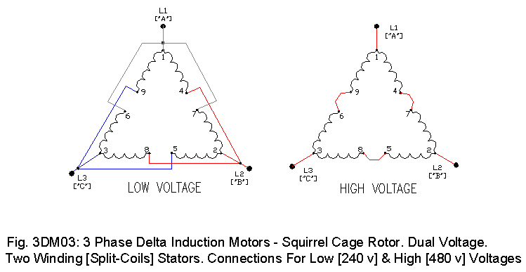
Thermal contacts tb white m 1 z2. With the motor disconnected from the load the speed will be close to 1500 rpm regardless of the connection. Wiring diagram for two speed moto explained. Diagram dd6 diagram dd7 m 1 ln e diagram dd8 ln e l1 l2 l3 sc z1 u2 z2 u1 cap. Diagram dd6 diagram dd8 m 1 ln e diagram dd9 m 1 ln e white brown blue l1 l2 n sc bridge l1 and l2 if speed controller sc is not required diagram dd7 ln e l1 l2 n sc z2 u2 z1 u1 cap. If all that is correct the diagram below would be the complete connection diagram.
Single phase motor wiring diagram forward reverse single phase motor wiring diagram with capacitor start throughout rh natebird me.


