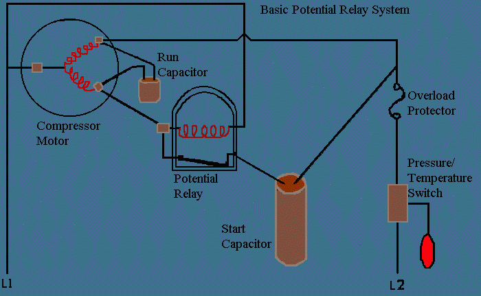
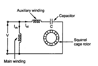
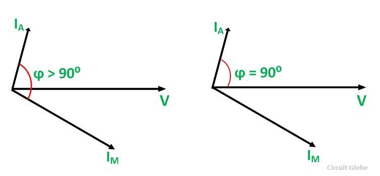
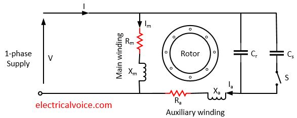
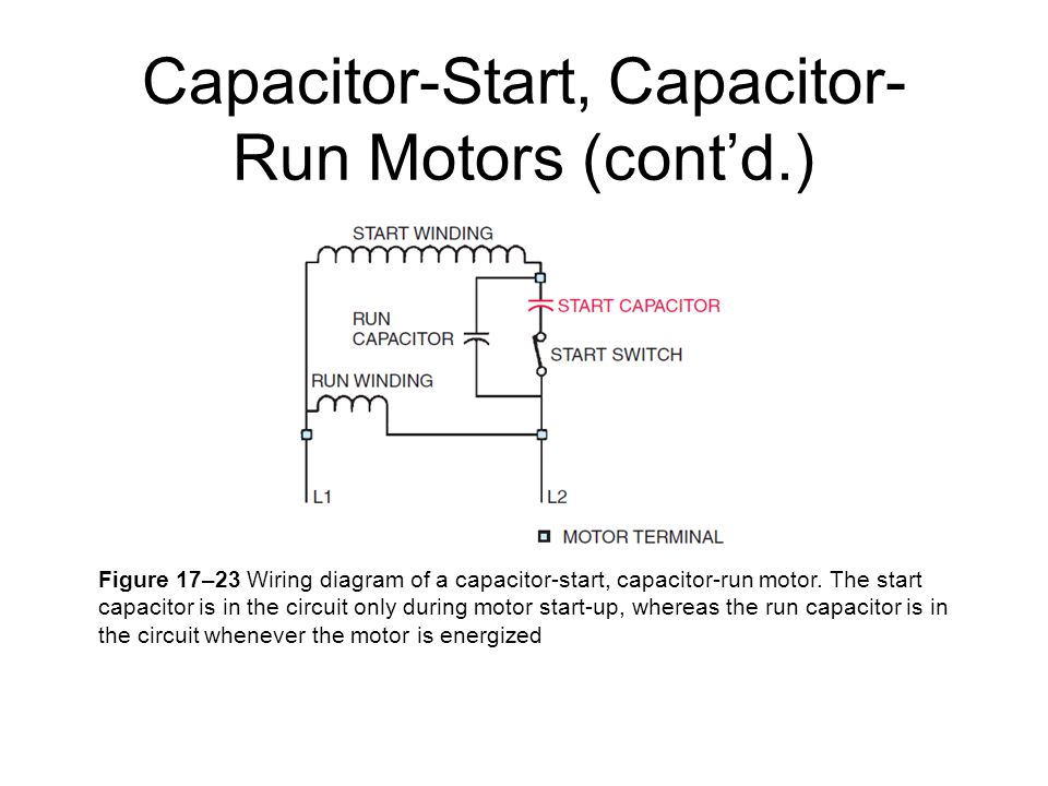
One often used method is the split phase motors. Run capacitor at the top start capacitor at the bottom.
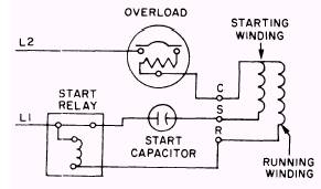
Single Phase Hermetic Motors
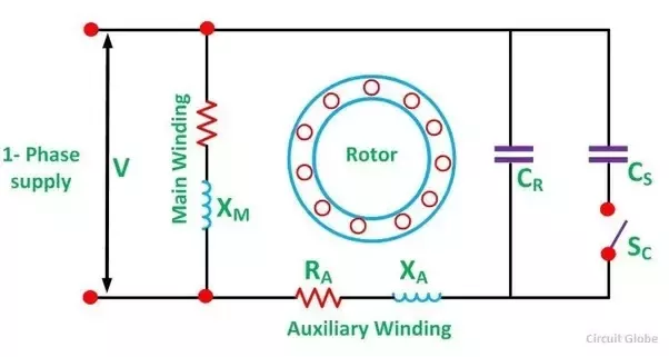
Single phase capacitor start capacitor run motor connection. L1 and l2 are designated as the two connection points representing the two electricity flow path inherent with single phase circuits where a single phase supply voltage is fed to the motors internal circuit. Wiring diagram not just offers in depth illustrations of whatever you can do but additionally the processes you should stick to although carrying out so. We know about the activity of a capacitor in a pure ac. For starting a single phase motorit required a high capacitance of capacitor for a high starting torque start capacitors are designed for momentary usegenerally this type of motor used a centrifugal switch or potential relay to disconnected this when approximately 34 the speed is reached to avoid overloads of the auxiliary winding. The single phase induction motor can be made to be self starting in numerous ways. Single phase capacitor start capacitor run motor wiring diagram single phase motor wiring diagram with capacitor.
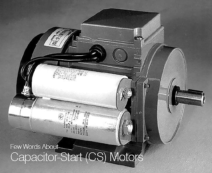
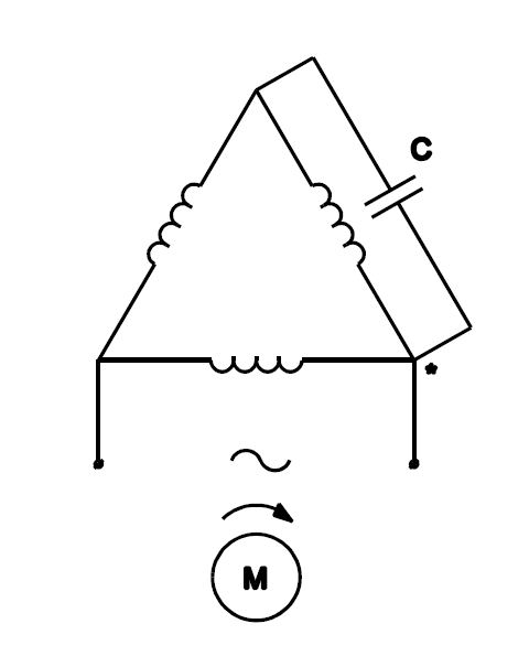
Another method is the capacitor start induction run motors. Single phase motor wiring diagram with capacitor start capacitor run. Switching the link positions reverses the winding phases relative to each other reversing the direction of rotation. This gives the following circuit diagram.

