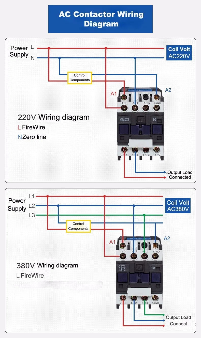
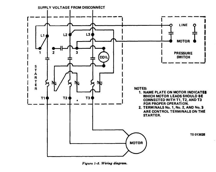
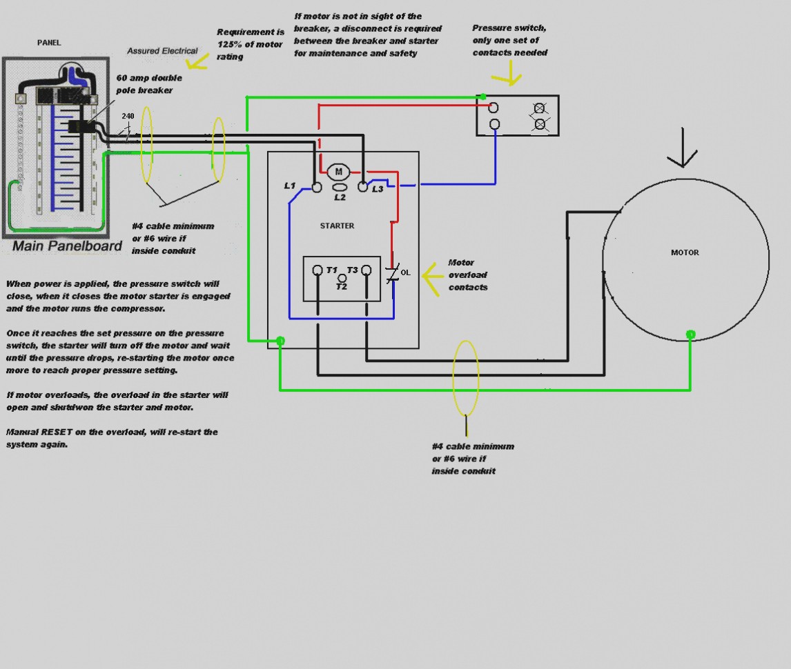
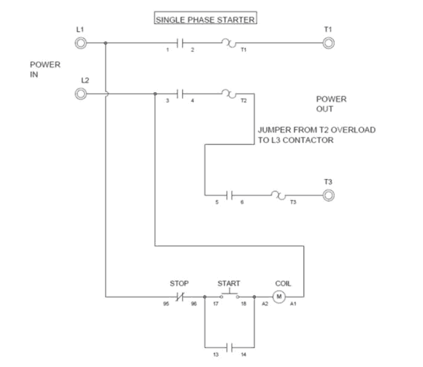
How do i do a wiring to a single phase contactor via photocell to the outside lights. In the above one phase motor wiring i first connect a 2 pole circuit breaker and after that i connect the supply to motor starter and then i do cont actor coil wiring with normally close push button switch and normally open push button switch and in last i do connection between capacitor.
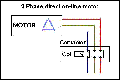
Contactors And Control Circuits
Single phase contactor wiring diagram. The lights connect to the output ports on the contactor. Single phase dol starter wiring diagram animation duration. The start and stop circuits could alternatively be controlled using a plc. Why 3 phase ac instead of single phase. My creative engineering 3187 views. Wiring diagram since wiring connections and terminal markings are.
It uses a contactor an overload relay one auxiliary contact block a normally open start pushbutton a normally closed stop pushbutton and a power supply with a fuse. Wiring diagram pics detail. The black power wires will need to be tied together. Collection of single phase motor starter wiring diagram. Home about us news wiring a single phase motor through a 3 phase contactor. Contactor breakers limit switch no static control standard elementary diagram symbols.
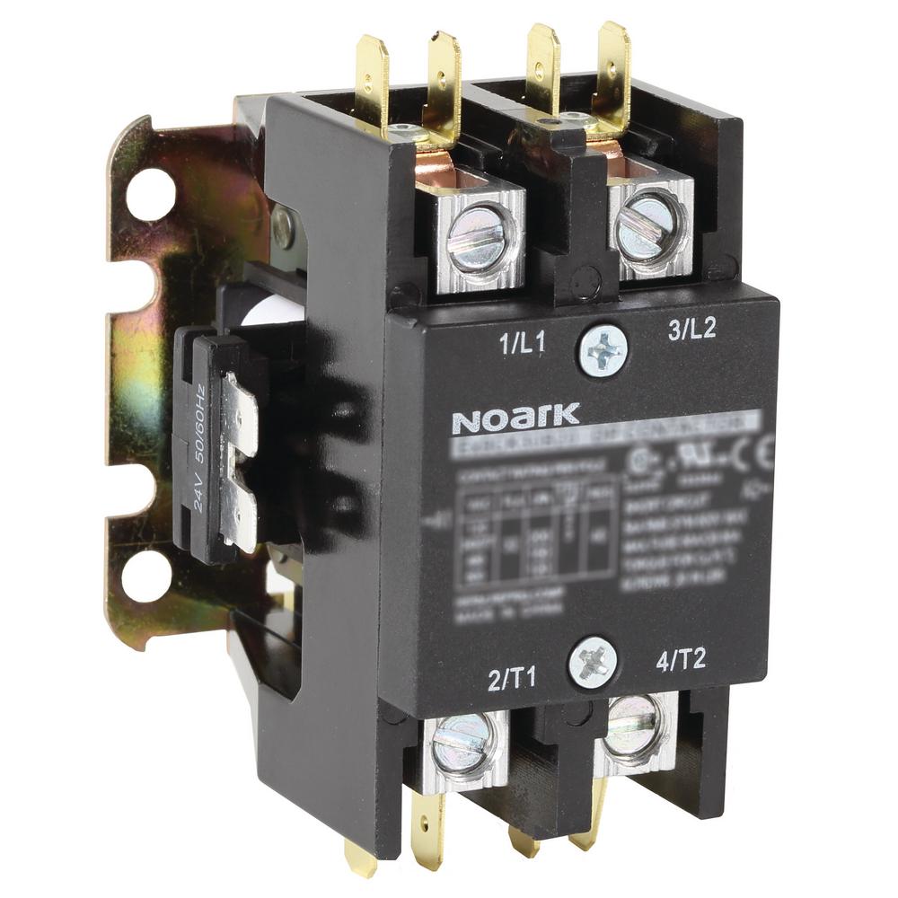
Electrical wiring for single phase motor controls tobi a motor control is simply a relay contactor that acts as a switch which is activated by a different power source or a control circuit. With this kind of an illustrative guidebook you will be capable of troubleshoot prevent and complete your projects without difficulty. The contactor will have space for the red power wires coming in from the photocell circuit breaker and lights. Single phase reversing contactor wiring diagram. 4 table 2 nema and iec terminal markings. How to wire contactor and motor protection switch direct on line starter.
Single phase power is typically reserved for lower power requirements however in some cases powering a small motor with single phase input power is practical. Single phase dwelling services101 table 12 awg and metric wire data 102. The above diagram is a complete method of single phase motor wiring with circuit breaker and contactor. This diagram is for single phase motor control. Posted january 18 2018 by springercontrols. In the above one phase motor wiring i first connect a 2 pole circuit breaker and after that i connect the supply to motor starter and then i do cont actor coil wiring with normally close push button switch and normally open push button switch and in last i do connection between capacitor.
Wiring a single phase motor through a 3 phase contactor. The control circuit may be operated manually or automatically when the control circuit is wired through sensors or other control devices. Contactor wiring diagram you will want a comprehensive professional and easy to know wiring diagram. Single phase motor starter wiring diagram wiring diagram for motor contactor best wiring diagram motor fresh single phase motor starter wiring.


