Single phase motor wiring diagram with capacitor sources. In this post i am explaining the type one below i shown the single phase manual changeover switch with image and connection manual changeover switch wiring diagram with complete connection of main supply and generator supply and out going supply to the load.
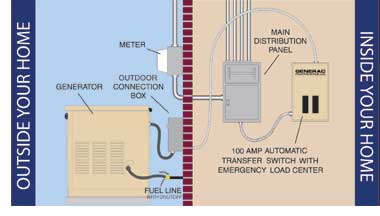
Generator Transfer Switch Buying And Wiring
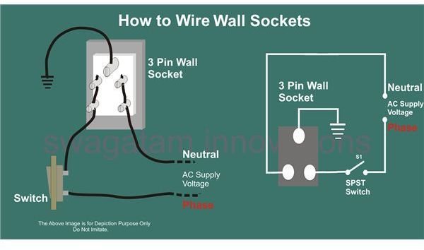
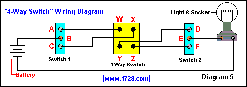
Single phase main switch connection diagram. These two lines line and neutral from energy meter are. In the above one phase motor wiring i first connect a 2 pole circuit breaker and after that i connect the supply to motor starter and then i do cont actor coil wiring with normally close push button switch and normally open push button switch and in last i do connection between capacitor. The above diagram is a complete method of single phase motor wiring with circuit breaker and contactor. Here is a picture gallery about single phase forward reverse motor wiring diagram complete with the description of the image please find the image you need. In this video i try to explain the concept of single phase electrical meter or single phase energy meter. In fig 2 different connection and wiring diagrams are shown for a two pole single phase manual changeover switch.
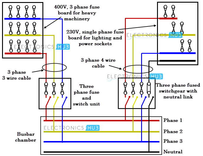
In this single phase home supply wiring diagram the main supply single phase live red wire and neutral black wire comes from the secondary of the transformer 3 phase 4 wire star system to the single phase energy meter note that single phase supply is 230v ac and 120v ac in us. Wiring diagram for single phase motor fresh pretty single phase. Types of single phase induction motors electrical a2z single phase induction motors are traditionally used in residential applications such as ceiling fans air conditioners washing machines and refrigerators single phase motor wiring with contactor diagram the plete guide of single phase motor wiring with circuit breaker and contactor diagram. The upper portion of the changeover switch is directly connected to the main power supply while the lower first and right connections slots are connected to the backup power supply like generator or inverter. After watching this video you can make the connection of electricity meter at home. Split phase motors usually operates at 120 hp to 13 hp.
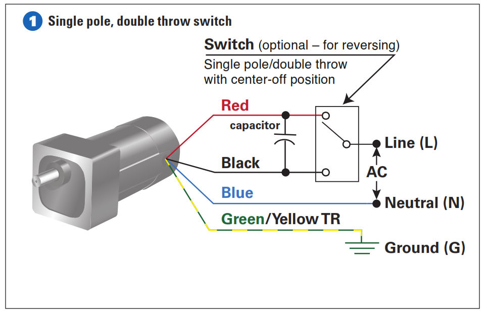
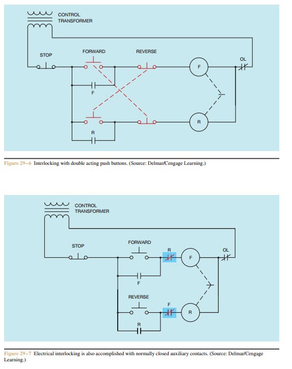
With single phase motor with capacitor forward and reverse wiring. Single phase motor wiring diagram with capacitor start. A split phase induction motor is a single phase induction motor that has two windings called the run winding and a secondary start winding and a centrifugal switch as shown in figure 6. Three phase motor connection stardelta y δ reverse forward with regard to single phase forward reverse motor wiring diagram image size 621 x 686 px and to view image details please click the image. Single phase motor wiring diagram forward reverse collections of phase meter wiring diagram single phase motor capacitor wiring. Single phase db wiring diagram single phase meter wiring diagram energy meter mcb connection input and output real mcb connection how to mcb box connection distribution mcb box.

