Single phase motor starter wiring diagram pdf a novice s overview of circuit diagrams. The single phase induction motor is much the same in construction as the three phase motor.

Wiring Magnetic Definite Purpose Starters For Compressor
Single phase starter wiring diagram pdf. Wiring capacitors resistors semiconductors table 1 standard elementary diagram symbols contd iron core air core auto iron core air core current dual voltage thermal magnetic single phase 3 phase squirrel cage 2 phase 4 wire wound rotor armature shunt field show 4 loops series field show 3 loops commutating or compensating field show 2. Wiring of the direct on line dol motor starter 1 three phase supply 230volt coil see wiring diagram. All other control and power connections have to be made by the installer. 1 the following links are pre fitted to the starter. It reveals the parts of the circuit as simplified shapes and the power and signal links between the gadgets. This diagram is for single phase motor control.
The function is the exact same. Assortment of single phase motor starter wiring diagram pdf. Figure 17 3 shows a very basic one line diagram of the single phase motor. Single phase motor wiring diagram with capacitor baldor single phase motor wiring diagram with capacitor single phase fan motor wiring diagram with capacitor single phase motor connection diagram with capacitor every electrical arrangement is made up of various unique pieces. In the above one phase motor wiring i first connect a 2 pole circuit breaker and after that i connect the supply to motor starter and then i do cont actor coil wiring with normally close push button switch and normally open push button switch and in last i do connection between capacitor. A wiring diagram is a streamlined traditional photographic representation of an electrical circuit.
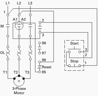
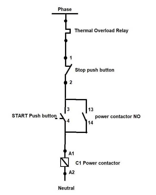
It uses a contactor an overload relay one auxiliary contact block a normally open start pushbutton a normally closed stop pushbutton and a power supply with a fuse. The above diagram is a complete method of single phase motor wiring with circuit breaker and contactor. Each component ought to be placed and linked to different parts in particular manner. Most induction motors are started directly on line but when very large motors are started. Apr 4 2018 single phase forward reverse motor wiring diagram 1. Some single phase induction motors are also called.
A2 14 18. The start and stop circuits could alternatively be controlled using a plc. Apr 4 2018 single phase forward reverse motor wiring diagram 1. Apr 4 2018 single phase forward reverse motor wiring diagram 1. Literally a circuit is the course that allows power to. A wiring diagram is a simplified traditional photographic representation of an electric circuit.
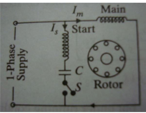
Refer back to this diagram as the operational requirements of the single phase motor are discussed. Collection of single phase motor starter wiring diagram. A very first look at a circuit diagram could be complicated yet if you can read a metro map you can review schematics. It reveals the components of the circuit as simplified forms as well as the power and also signal connections between the devices. 13 17 with a flying lead to be connected to overload terminal 95. Obtaining from point a to direct b.

