Single phase transformer primary and secondary wiring product line. Wiring diagram since wiring connections and terminal markings are shown this type of diagram is helpful when wiring the.

Transformer Wiring Diagram Single Phase Wiring Diagram
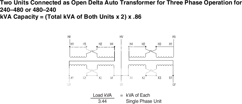
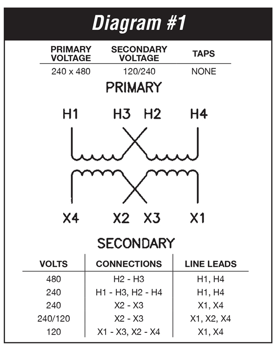
Single phase transformer wiring diagram. Forming a 3 phase transformer using single phase transformers. Capacitor start capacitor run induction motors are single phase induction motors that have a capacitor in the start winding and in the run winding as shown in figure 12 and 13 wiring diagram. Product connect a jumper between the h2 and h3 terminals and bring the v in on h1 h4. For a single phase transformer with dual 120v secondaries to derive a 240120v system with a neutral connect terminals x2x3 which will then be the neutral terminal. The connection diagram on the left shows how a deltadelta connection can be made either with three single phase transformers or with one three phase transformer. Neutral x0 provided on three phase 4 wire primary volts delta transformers 15 kva through kva are equipped with a volt lighting tap.
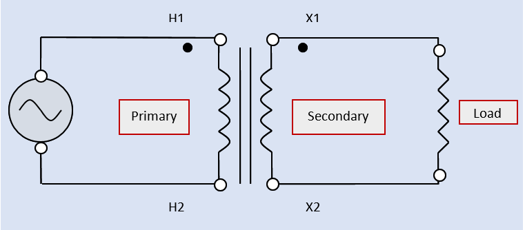
Applies to energy efficient ee type transformers by squaredschneider electric cause. Transformers are delivered in an unconnected condition and must be configured for the system need. Phase shift and phase polarity between two windings of a single phase transformer depends on how the windings are wound on the core. 240v will be available between x1 and x4. Typically a single phase transformer wiring schematic has a dot on both the primary and secondary windings. For example distribution transformers are normally wound with the secondary or low voltage windings that can be connected in series or parallel.
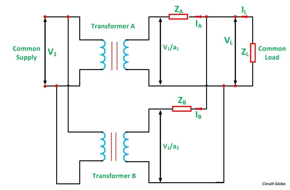
Transformer phase shift and transformer polarity needs to be considered for many applications some of which are. This type of motor is designed to provide strong starting torque and strong running for applications such as large water pumps. Single phase transformers like other electrical devices may be connected into series or parallel arrangements. 120v will be available from either x1 or x4 to the x2x3 neutral terminal. Parallel operation of transformers. The placement of these dots next to the ends of the primary and secondary windings informs us that the instantaneous voltage polarity seen across the primary winding will be the same across the secondary winding.
The dashed lines indicate the transformer outlines. Single phase transformer primary and secondary wiring. Single phase dwelling services101 table 12 awg and metric wire data 102. Transformer disconnects98 class 907098 enclosure selection guide99.


