Three phase slip ring rotor starter control diagram control diagram. For an induction motor to produce torque at least some difference should be there between stator field speed and rotor speed.
Starting Methods For Polyphase Induction Machine Electrical4u
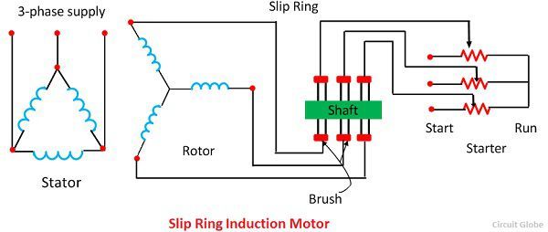
Slip ring induction motor connection diagram. When the motor is running the slip ring are shorted by connecting a metal collar which connects all slip ring together and the brushes are also. In this video you will learn connection of slip ring motor with starter panel serenity by audionautix is licensed under a creative commons attribution licenc. The slip ring induction motor diagram is shown below. Rev for three phase motor connection power and control diagrams. An electrical diagram of a slip ring three phase induction motor is shown below. The slip ring induction motor could be used for industrial wires where variable speed and high starting torque are prime requirements.
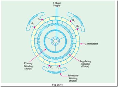
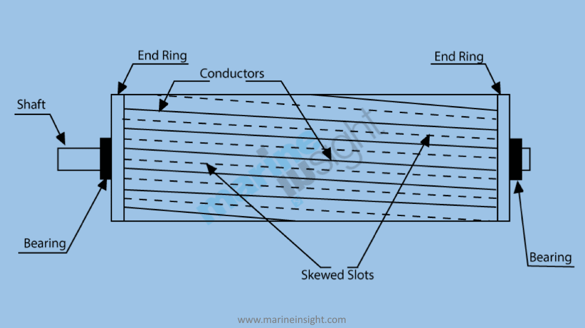
The function of a three phase slip ring induction motor is shown in the. The stator of slip ring induction motor is very much the same as that of the squirrel cage induction motor but the construction of its rotor is very much differentstator winding can be either star or delta connected depending upon the design. Three phase slip ring rotor starter control power diagrams 3 phase slip ring rotor starter control power diagrams slip ring rotor power and control. A slip ring is an electromechanical device that allows the transmission of power and electrical signals from a stationary to a rotating structure. Slip is defined as the difference between the flux speed and the rotor speed. Slip ring induction motor connection diagram why slip rings are used in an induction motor.
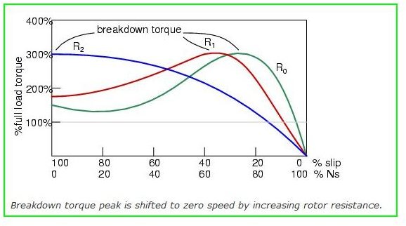
To increase the phase difference the motor is provided with some rings through which high resistance is connected in series with the circuit. The frame voltage is the open circuit voltage when the rotor is not rotating and gives the measure of turns. At starting the resistance is connected to the rotor circuit and is gradually cut out as the rotor pick up its speed. The slip ring induction motor has two distinctly separate parts one is the stator and other is the rotor. It can improve mechanical performance simplify system operation and eliminate damage prone wires dangling from movable joints. The phase difference between the current and voltage is not sufficient to develop high starting torque.
A slip ring can be used in any electromechanical system that requires rotation while transmitting power or signals. The stator circuit is rated as same in the squirrel cage motor but the rotor is rated in frame voltage or short circuit current.
Gallery of Slip Ring Induction Motor Connection Diagram