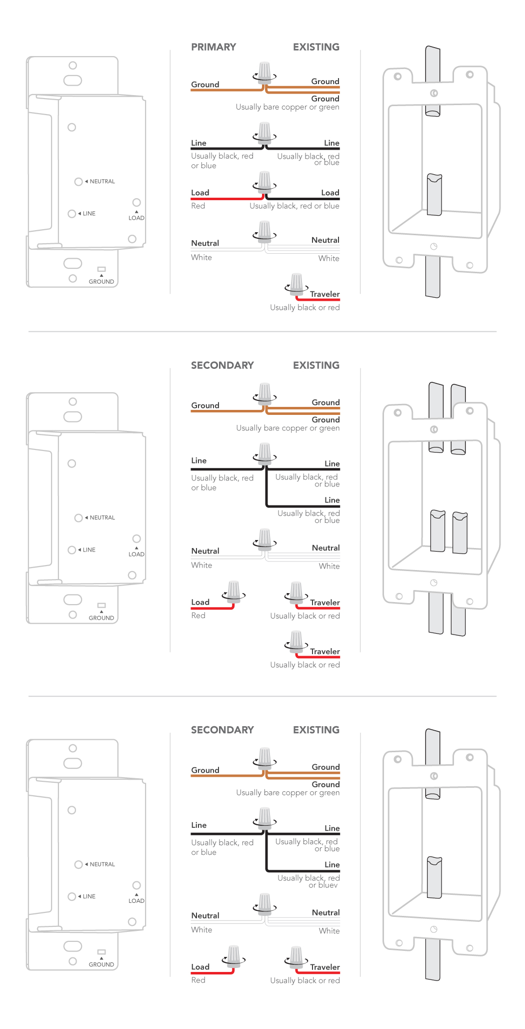
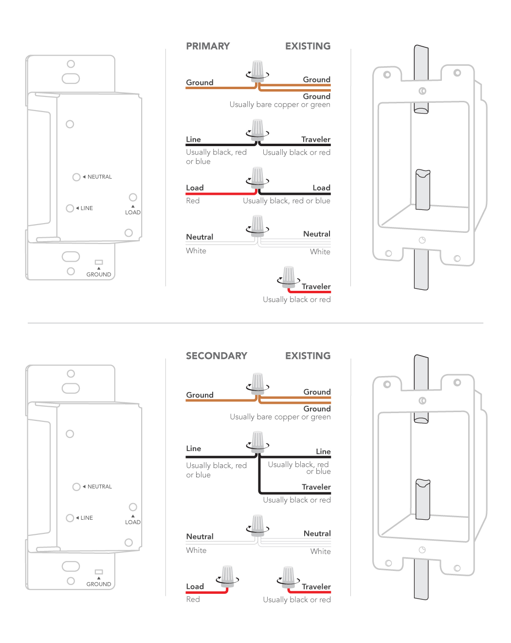
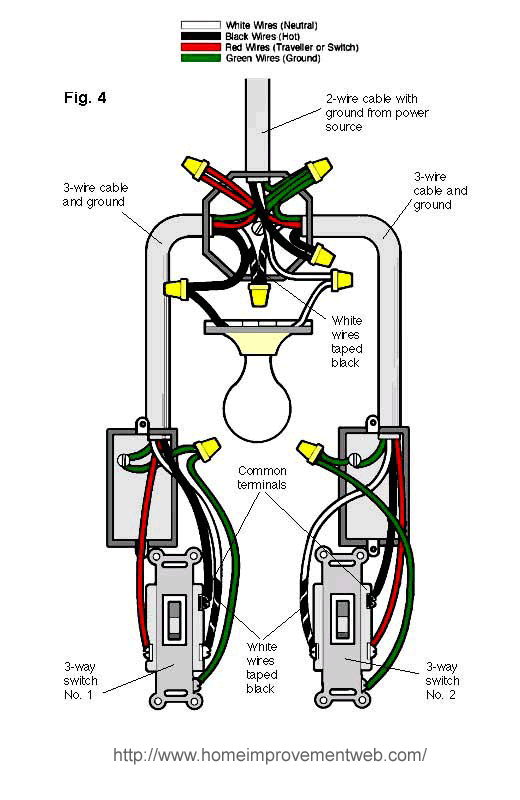
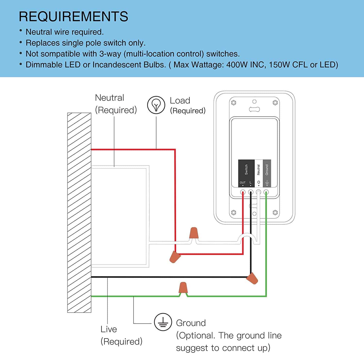
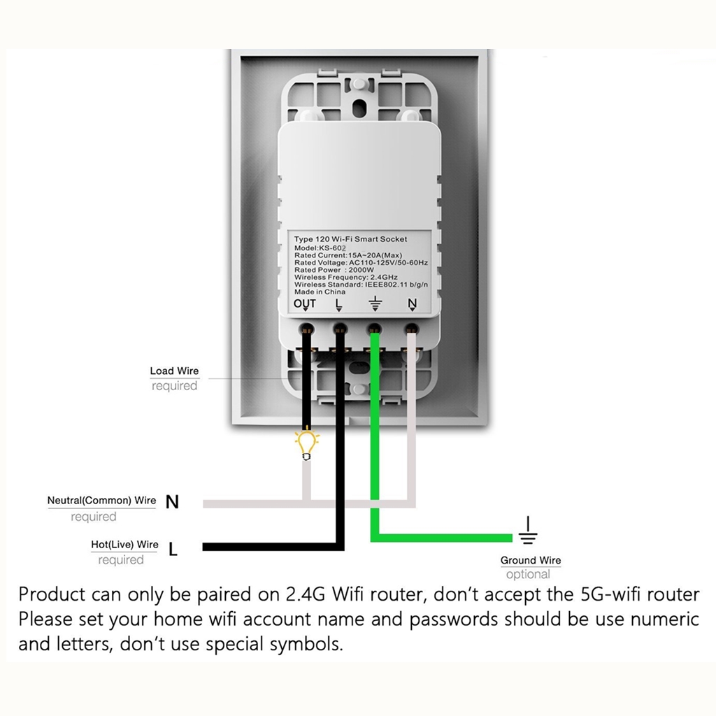
Connect each of the two black wires from the switch to the available live lines via the wire nut and wrap electrical tape around the wire nuts to make sure the copper conductor is fully concealed. Variety of generac smart switch wiring diagram.

Smart Wifi Light Switch With Remote Control And Timer
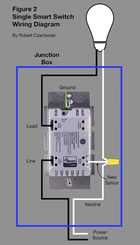
Smart switch wiring diagram. In the diagrams below the dotted rectangle represents a smart switch. Below is a diagram of a smart switch. Wiring diagram for 20kw generac generator fresh generac smart switch generac smart switch wiring diagram beautiful generac generac generator transfer switch wiring diagram image. The ground wire from the smart switch needs to be connected to that. In your switch box you should have one or more grounding conductors spliced together with a wire connector or wire crimp. Smart switch with neutral.
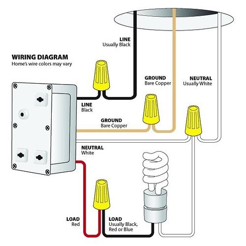
Wiring diagram of a wemo wifi switch with red for load black for line white for neutral and a yellow connected to a green ground wire. The switch still breaks the circuit but in this case the smart switch can tap into the neutral wire to keep power flowing through the switch the electronics in the switch still break the circuit to the light but the switch maintains a circuit so it is always receiving power. Otherwise the smart switch will be unable to power its wireless communication. Here is a diagram of a standard switch with a neutral wire. Smart light switch designs can vary but dont be afraid if they look different from. Green wire on switch ground line to ground line white wire.
That means there needs to be power running through r1 at all times. Step 4connect the smart switch wiring with the provided wire connectors as follows. Read the smart light switchs instruction manual thoroughly to ensure you understand its wiring and setup. R1 represents the load required to power the smart switch. Click on the image to enlarge and then save it to your computer by right clicking on the image.
