Also the circuit diagram is at around 418 or just at the end of the video. Its will turn on and turn off based on a loud sound such as clapping your hands.

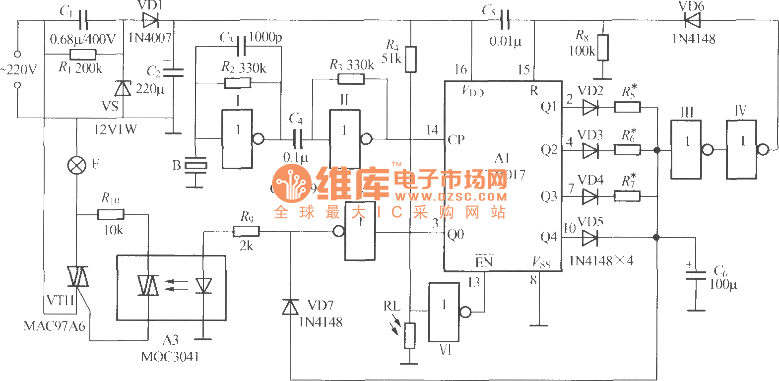
Fg 0939 Sound Operated Switch Circuit
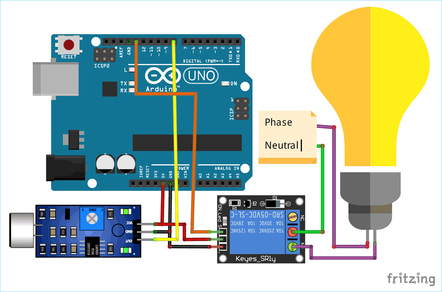
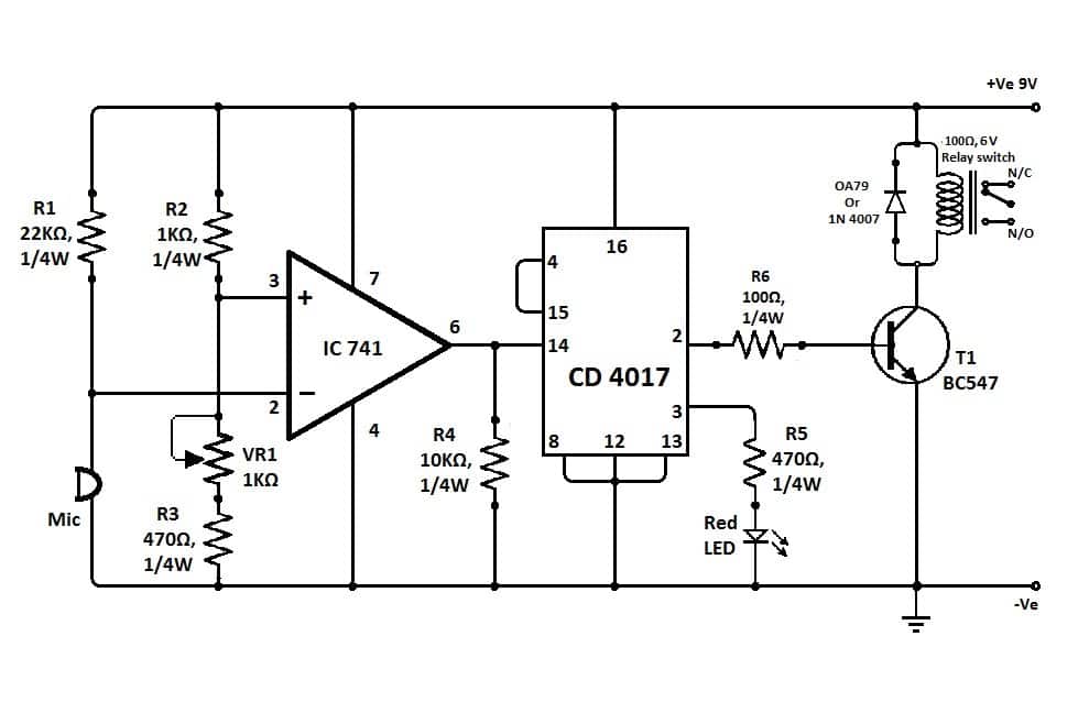
Sound switch circuit diagram. Following are the steps that you should follow to make this circuit work sound is received by an electret mic which converts these sound signals into electrical signals. The sound sensor and the relay module is powered by the 5v pin of the arduino. The discussed sound activated alarm circuit will work with any supply in between 6 and 12 however if the alarm is a powerful one the current might have to be selected accordingly. This circuit is operating on 9 12v dc. The output pin of the sound sensor is connected to the digital pin 8 of the arduino this is because of the. Very practical for a variety of projects.
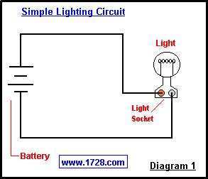
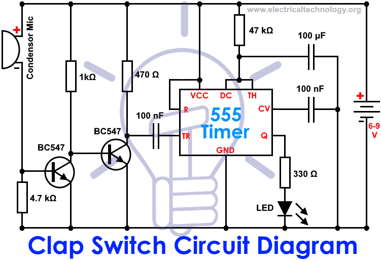
A clap switch is an electronic device that works based on clapping action it converts sound energy into electrical pulses and proved these electrical pulses as input to the control circuit for controlling the light. This circuit amplifies that output and feeds it to a monostable circuit that makes the led turn on for a bit. Clap switch is an interesting hobby circuit which turns on the lights with a clap sound. The ic has a lot of good features due to which it can be used in variety of sensor circuits. Lm358n is a dual high gain opamp ic contains two independent opamp in one package. Siris there any circuit diagram u knowthat can turns the house light on when c clap sound is appears n remains constantn also turns d light off with any sound or a clapif u know about dis then plezz make for me circuit diagram for men send it to my e mail d.
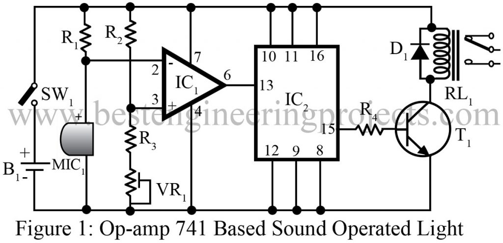
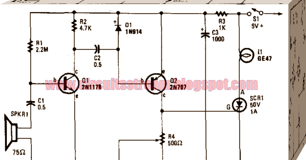
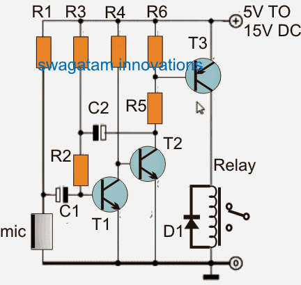
Circuit diagram working. This is a project of a sound sensor switch using lm358n ic. Working of this circuit is quite simple the main component is an audio amplifier lm386 ic. The output electric signal from microphone is very weak and need amplification which is done by transistor t 1 and t 2. The preset may be used for setting the sensitivity of the circuit. The circuit was drawn using fritzing software.
In the circuit sound operated on off switch microphone is used as sensor. Although its name is clap switch but it can be turned on by any sound of approximately same pitch of clap soundthe main component of this clap switch circuit is the electric condenser mic which has been used as a sound sensorcondenser mic basically converts sound energy into electrical energy. A switch is an electronic device that is used to connect or disconnect the power supply to the circuit. Mic 1 receives tone signal of 46 khz from tone generation or transmitter circuit and converts it into electric signal. The complete circuit diagram for the arduino whistle detector switch circuit using sound sensor is show below. This is a sound activated switch circuit.
You can adjust the sensitivity how loud of a sound will activate the circuit from a pin drop to a mack truck horn. Tone amplifier sound operated on off switch. 8 thoughts on sound activated switch ratnadeep march 3 2012.
Gallery of Sound Switch Circuit Diagram