Connect the spds neutral wire white to the systems neutral connection not required for. Installation shown with midnite solar e combiner box.
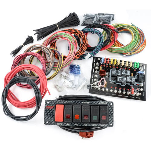
K R Switch Panel Wiring Diagram Wiring Diagram
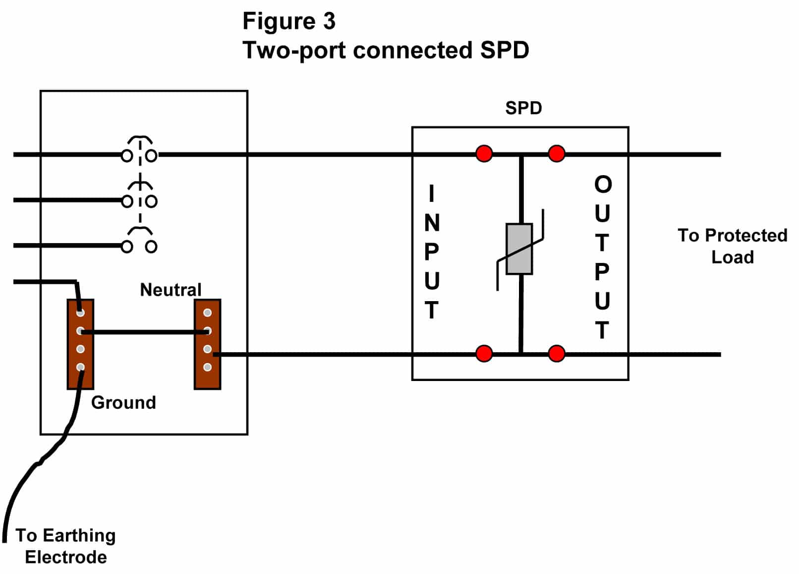
Spd wiring diagram. The conductors used to connect the spd to the line or bus shall not be any longer than necessary and shall avoid unnecessary bends wire the following represents a wiring diagram of spds in a typical system. Place the relays rated coil voltage on these terminals. Spd can be used with any electric panel that is within the spd ratings. The conductors used to connect the spd to the line or bus shall not be any longer than necessary and shall avoid unnecessary bends green wire the following represents a wiring diagram of spds in a typical system. This is the diagram below to learn all the pin terminals of a single pole double throw spdt relay. Each component ought to be set and linked to different parts in specific manner.
A higher energy spd is used between neutral and the protective conductor. Pv plus bus red wire battery negative black wire ground ac in blackred wire ac out blackred wire. This higher energy spd typically a spark gap for a type 1 spd is required as lightning currents arise towards the protective conductor and as such this higher energy spd sees up to 4 times the surge current of the spds connected between the live conductors. Connect the spds ground wire green to the systems ground connection. Single pole double throw spdt relay wiring diagram. The polarity of the voltage does not matter.
Locate the electrical systems applicable wiring diagram in section 23. Otherwise the structure will not work as it ought to be. The 2 coil terminals is where the voltage is placed in order to energize the coil. Hampton bay 3 speed ceiling fan switch wiring diagram hampton bay 3 speed ceiling fan switch wiring diagram every electrical structure is made up of various different parts. Reference this wiring diagram as necessary in steps 2 3 and 4.
