I run is the current in the main winding and i start is the current in the starting winding. A split phase capacitor start electric motor may be defined as a form of split phase motor having a capacitor connected in series with the auxiliary winding.
Circuit Diagram Of Split Phase Motor Download Scientific
Split phase motor diagram. Split phase induction motor. If you apply current to both windings and establish a magnetic field simul. Split phase motor diagram is shown in the figure. A split phase induction motor is a single phase motor consists of a stator and a single cage rotor. Split phase capacitor start electric motor. Thus there exists the time difference between the currents of the two windings.
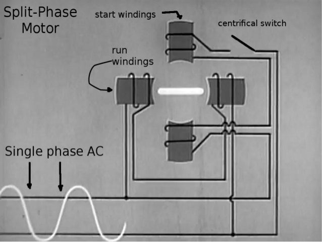
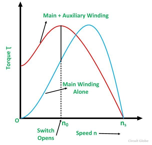
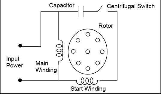
The starting winding is displaced 90 electrical from the main winding and operates only during the brief period when the motor starts up. The run and start stator windings are con nected in parallel. Main winding and an auxiliary winding. It shows the run and start winding of the stator as well as the centrifugal switch cs. The auxiliary circuit is opened by the centrifugal switch when the motor reaches 70 to 80 percent of synchronous speed. Psc motor typical wiring diagram for a psc motor definition and characteristics.
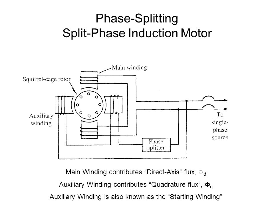
Figure 17 10 is a basic one line diagram of the split phase motor. Then how do the single phase motors what we use everyday are self starting. In construction these two windings are placed 90 apart in space. Psc means permanent split capacitor run capacitor permanently connected in. The stator has two windings ie. Thus a capacitor start induction run motor produces a better rotating magnetic field than the split phase motors.
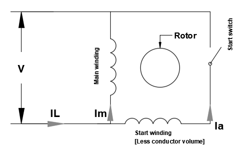
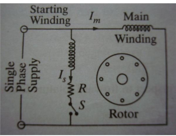
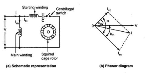
Also known as a capacitor run motor this type of motor uses a non polarized capacitor with a high voltage rating to generate an electrical phase shift between the run and start windings. The current in the auxiliary winding i a is approximately in phase with the line voltage. The angle between the two currents is φ as shown in the figure. Single phase motors are not self starting as the supply voltage is not producing a rotating magnetic field. The auxiliary winding is also known as starting winding. There is a centrifugal switch in the auxiliary winding circuit that opens as the motor approaches full speed.
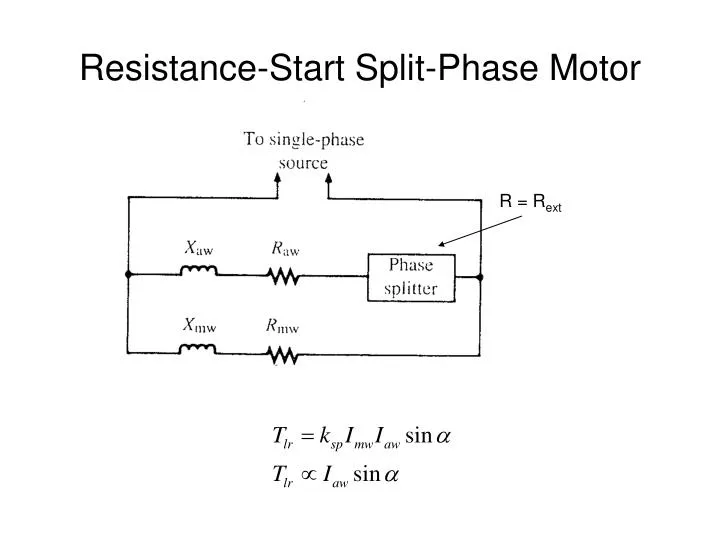
Read here to know about the split phase motor wiring arrangement and starting method of a single phase motor. It is important to point out from the phasor diagram that the phase difference between im and is is almost 80 degrees as against 30 degrees in a split phase induction motor. Figure 1 illustrates the split phase induction motor. The split phase motor relies solely on differences in the resistance and reactance of the windings to produce a phase shift. The stator of a split phase induction motor is provided with an auxiliary or starting winding s in addition to the main or running winding m to make the single phase induction motor self starting. The current in the main winding i m lag behind the supply voltage v almost by the 90 degree angle.
The phasor diagram of the split phase induction motor is shown below. Know the method used to reverse a single phase induction motor.
Gallery of Split Phase Motor Diagram