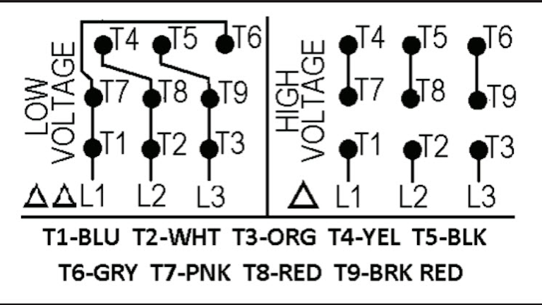
Inst maint wiringqxd 5032008 1002 am page 6. These diagrams are current at the time of publication check the wiring diagram supplied with the motor.
Electrical Wiring Diagram Forward Reverse Motor Control And
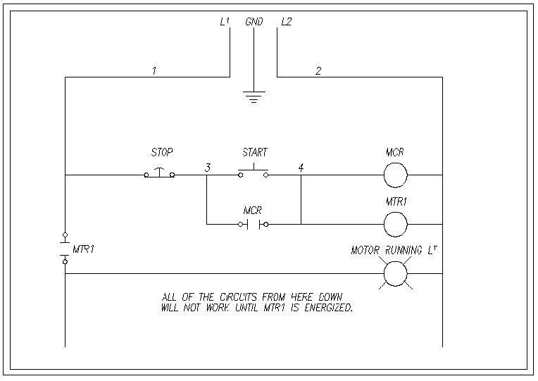
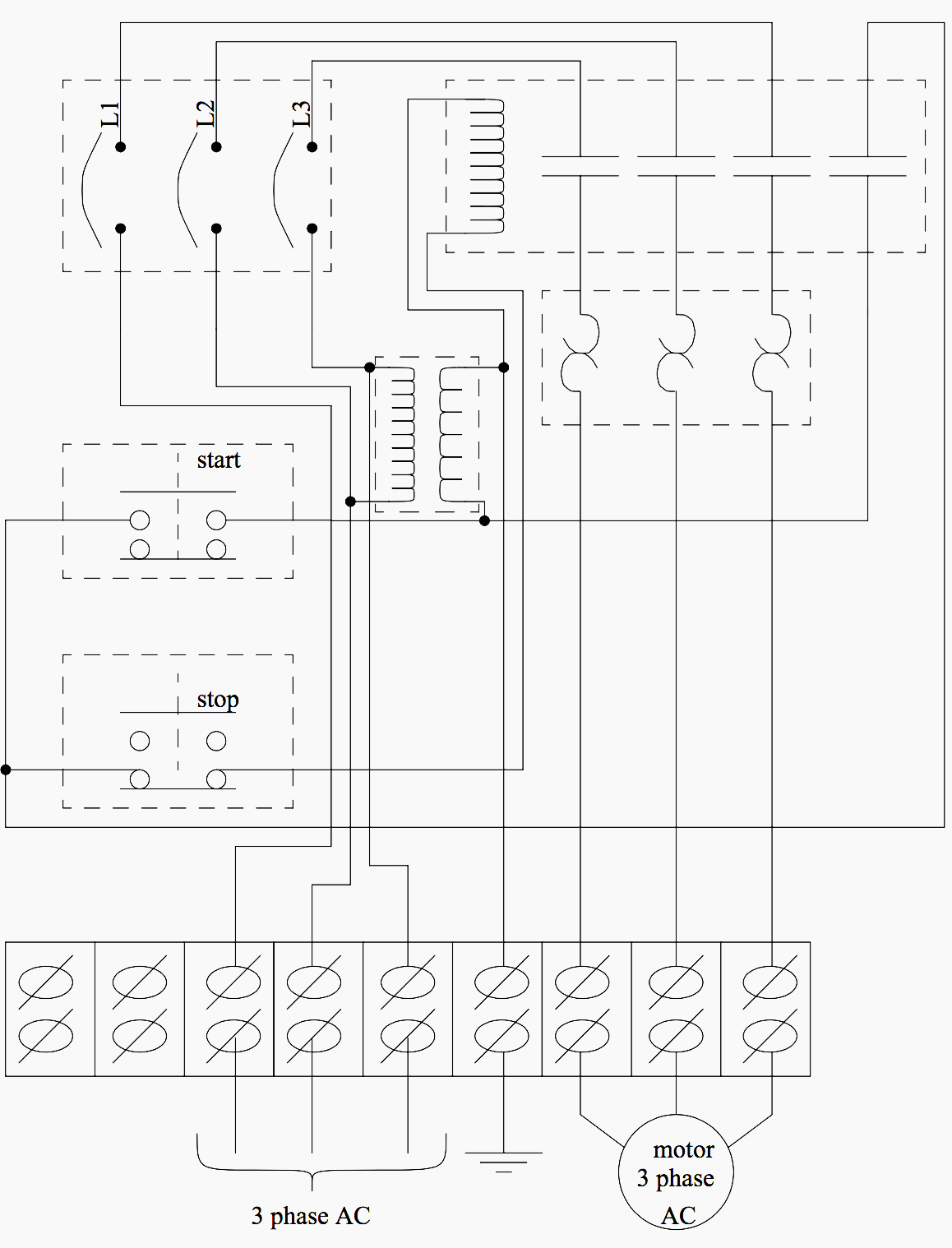
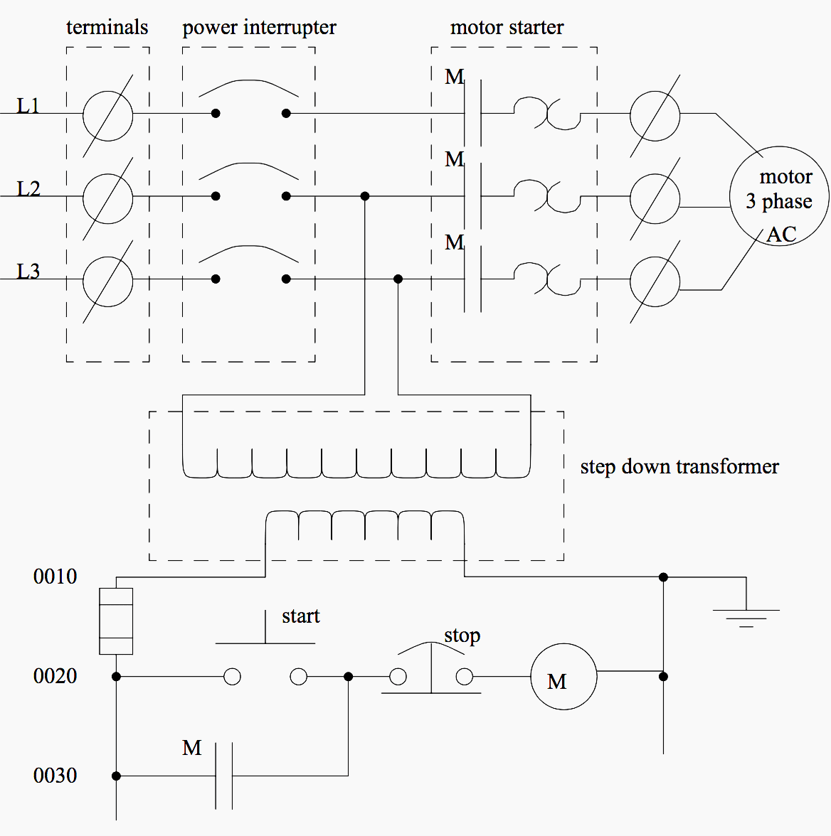
Standard motor control line and wiring diagram. Wiring diagrams show the connections to the controller. The control circuit may not be at the same voltage as the power circuit. Note the control circuit is a three wire ladder diagram control circuit which works well for smaller horsepower three phase motors. Basics 4 600 v 1 line. Basics 9 416 kv pump schematic. Basics 8 aov elementary block diagram.
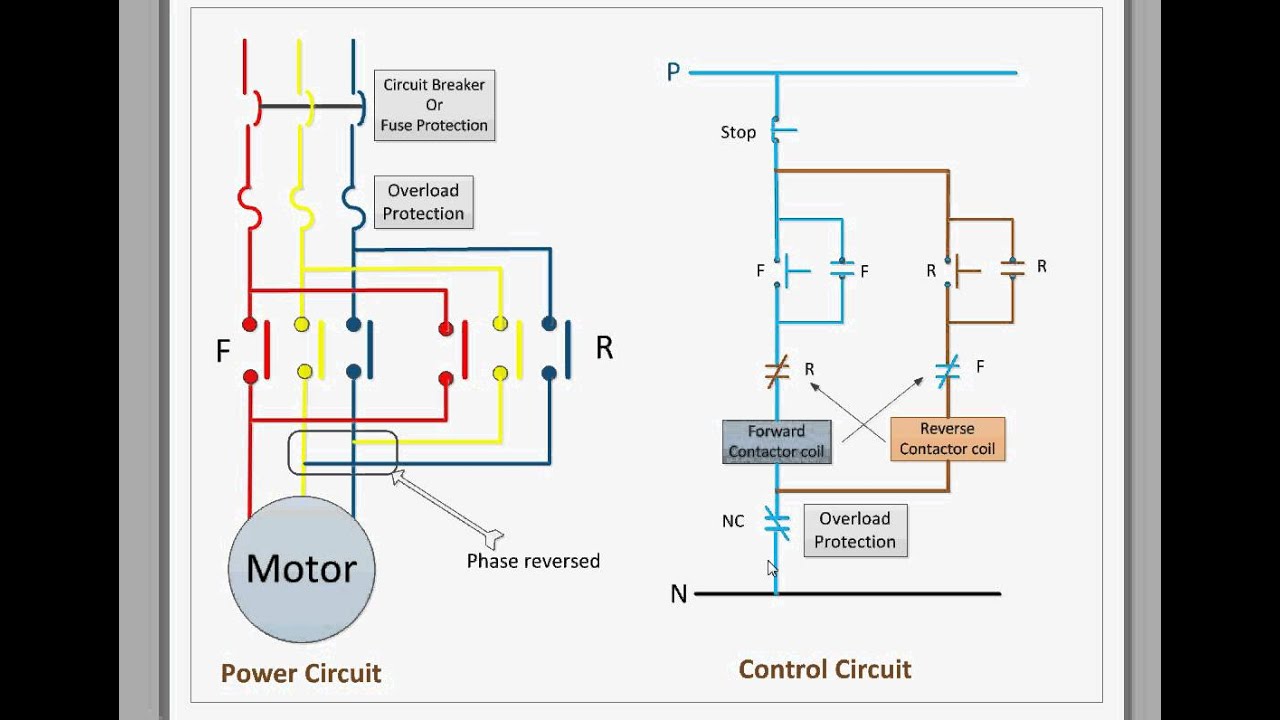
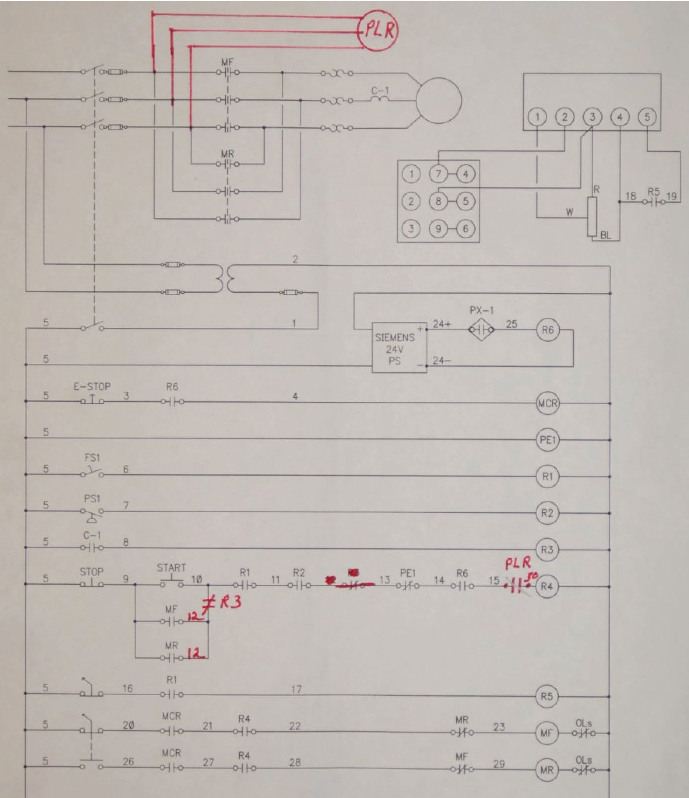
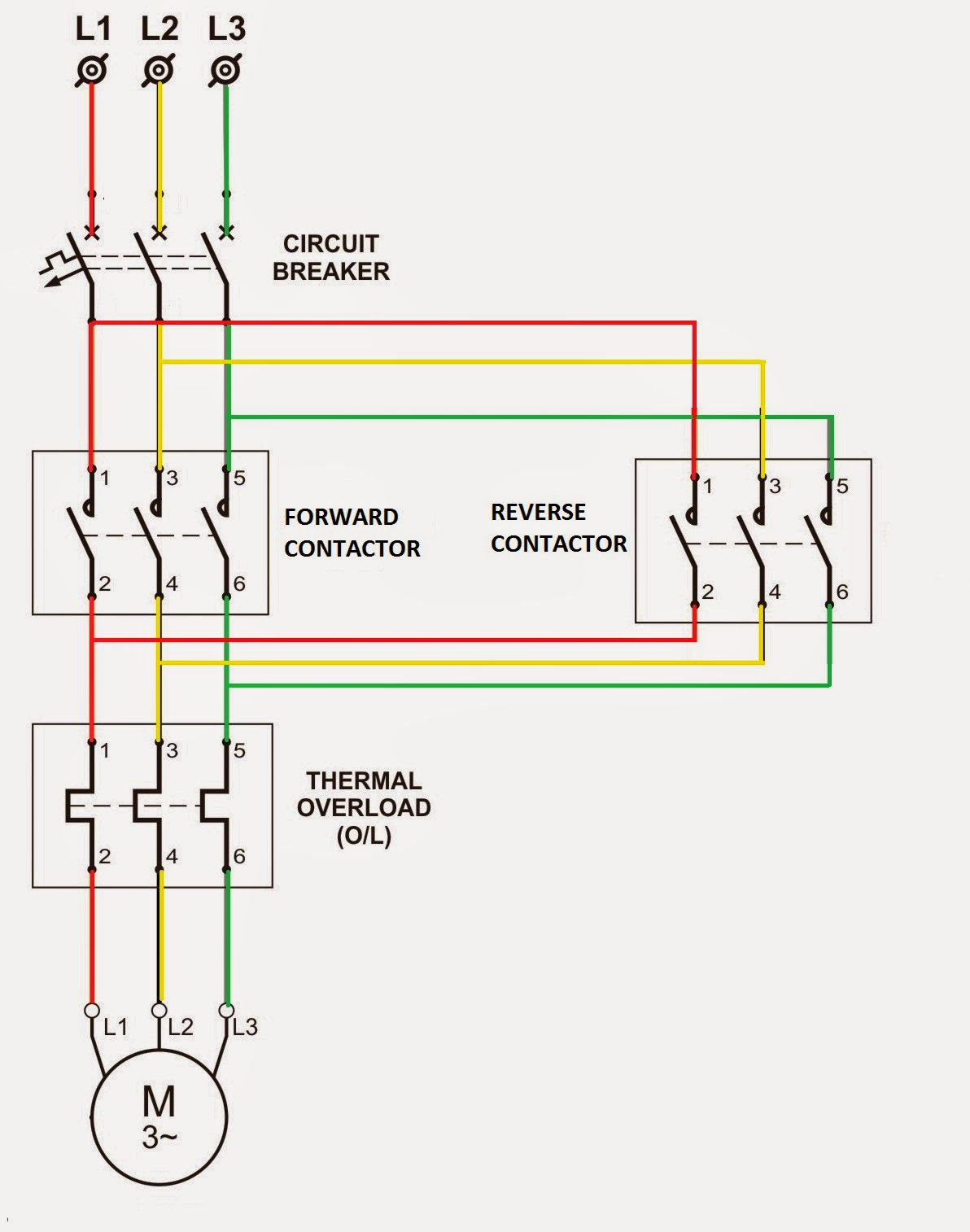
Full voltage reversing 3 phase motors. Rockis 2001 wiring diagrams wiring connection diagram a diagram that shows the connection of an installation or its component devices or parts. Wiring diagrams show as closely as possible the actual location of each component in a circuit including the control circuit and the power circuit. 65l injection pumps. Wiring diagrams sometimes called main or construction diagrams show the actual connection points for the wires to the components and terminals of the controller. Basics 11 mov schematic with block included basics 12 12 208 vac panel diagram.
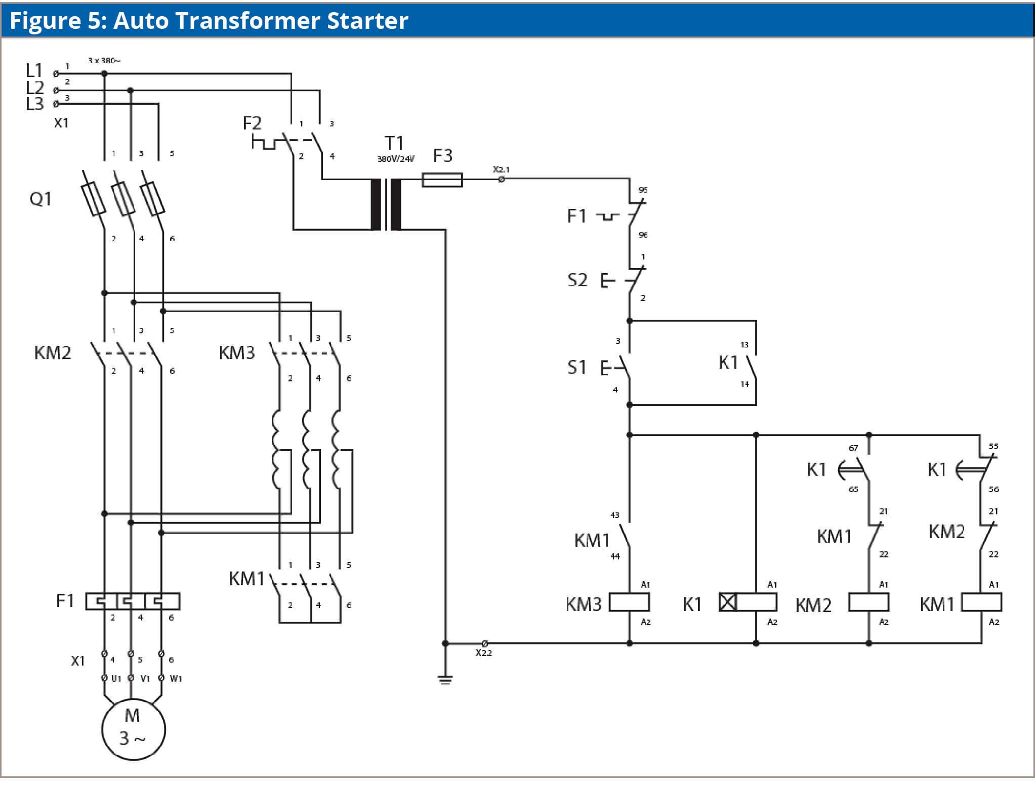
Basics 5 480 v mcc 1 line. Basics 6 72 kv 3 line diagram. When the voltage of the control and power circuits is the same it is referred to as common control. Basics 7 416 kv 3 line diagram. It uses two contactors two auxiliary contact blocks an overload relay a mechanical interlock two normally open start pushbuttons a normally closed stop pushbutton and a power supply with a fuse. The diagram for a typical full voltage across the line starting circuit is shown in figure 1.
Keep checking back as we continue to add additional products and categories. Basic wiring for motor control technical data. Refer to the motor manufacturers data on the motor for wiring diagrams on standard frame ex e ex d etc. Electric motor controls g. Basics 10 480 v pump schematic. Leading independent manufacturer and distributor of replacement parts for the automotive aftermarket since 1919.
This diagram shows both the power circuit and the control circuit. Typical starter wiring diagram three phase. This diagram is for 3 phase reversing motor control with 24 vdc control voltage. A wiring diagram gives the necessary information for actually wiring up a group of control devices or for physically tracing wires when trouble shooting is necessary. Basics 3 416 kv bus 1 line. If the volt ages are different it is called separate control.
A line diagram gives the necessary informa tion for easily following the operation of the various devices in the circuit. The control circuit is separate from the motor circuit. 65l diesel fuel injection pump 2002 94.
Gallery of Standard Motor Control Line And Wiring Diagram