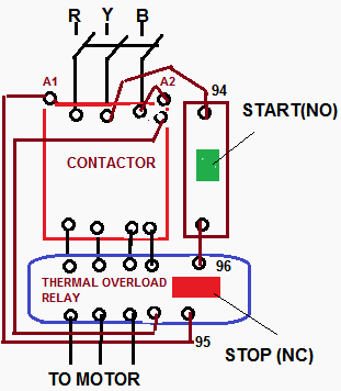
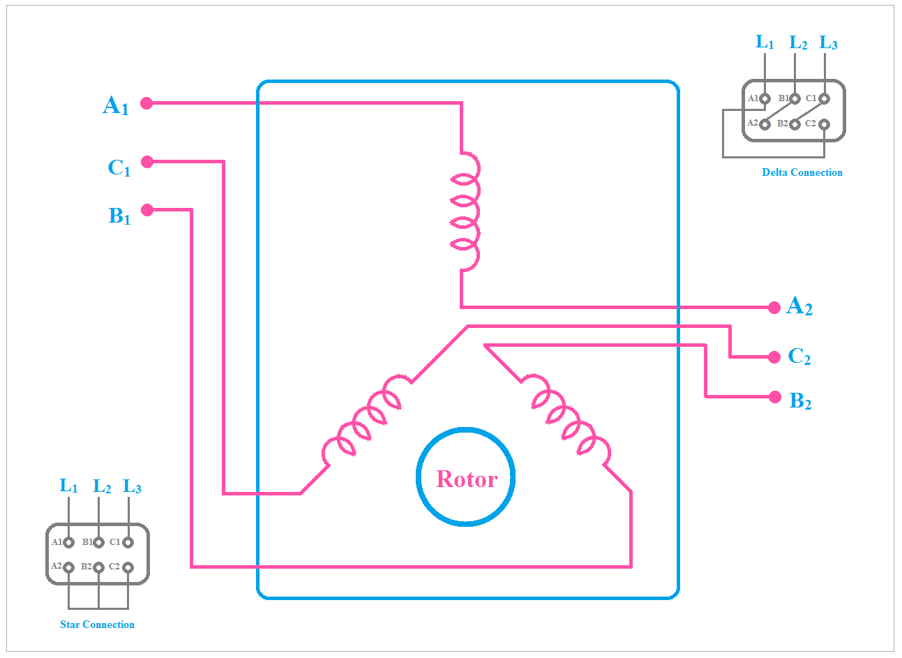
Star delta connection duration. When the fault occurs the thermal overload relay will trip the circuit.
Can You Show A Connection Diagram For A Star Delta Motor Quora
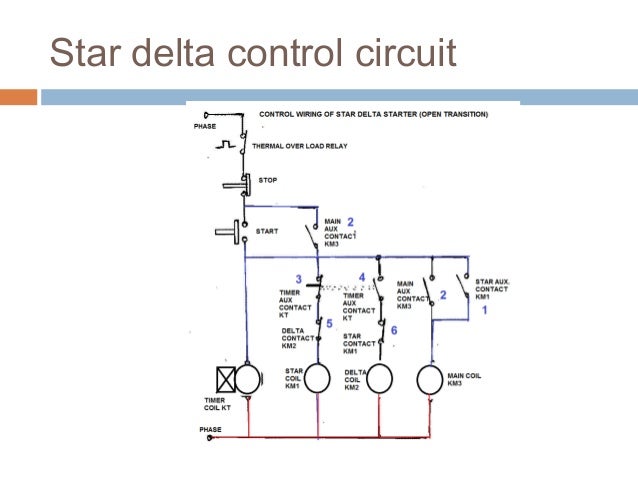
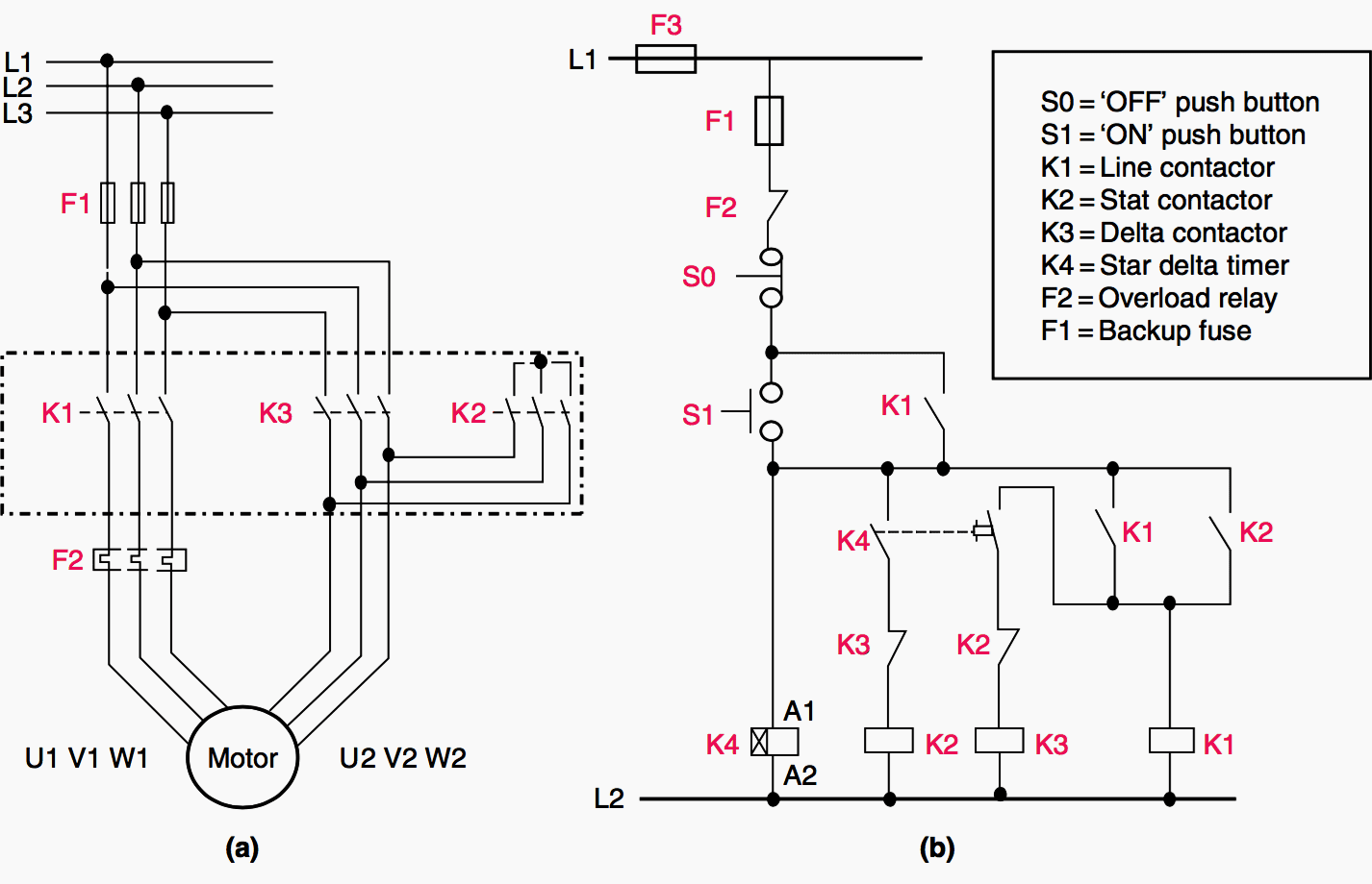
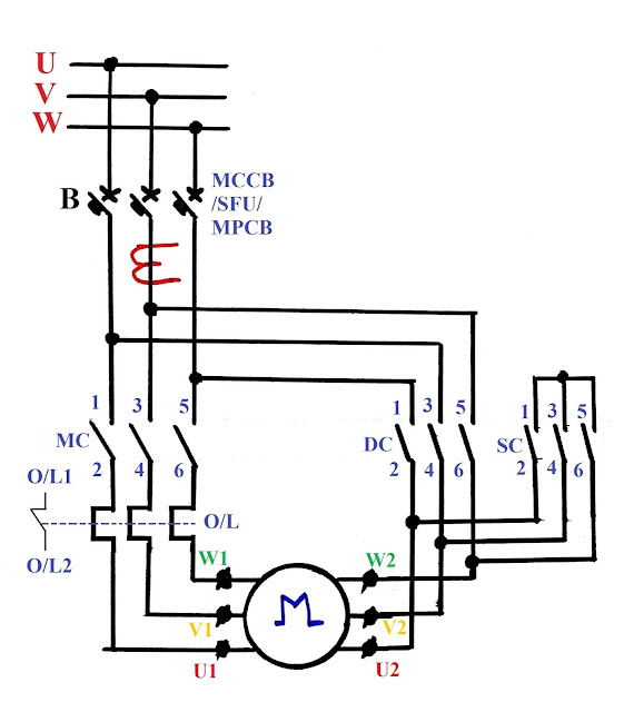
Star delta starter control circuit diagram explanation. The control circuit uses to control the starter circuit such as on off and tripping operations. Star delta connection circuit diagram. Star delta starters consist of a power circuit and control circuit. In this tutorial we will show the star delta y δ 3 phase induction ac motor starting method by automatic star delta starter with timer with schematic power control and wiring diagram as well as how star delta starter works and their applications with advantages and disadvantages. Refer to the below star delta circuit. Then once the motor reaches the required speed the motor is connected in through a delta connection.
Star delta starter control circuit diagram. There is minor correction is require to change printed in boxes sequence of 3 phase wires from w2 v2 u2 to w2 u2 v2 to get delta connection properly. In star delta starting an induction motor is connected in through a star connection throughout the starting period. Next the circuit goes through the nc terminals of the thermal over load relay. A star delta starter is the most commonly used method for the starting of a 3 phase induction motor. Ryb electrical 597548 views.
In the diagram of power circuit of star delta starter u2 and v2 of 3 phase motor should be connect to 4 and 6 respectively instead of u2 and v2 are connected to 6 and 4 of delta contector km2. As you see in the above star delta starter diagram first an nc push button switch is connected to stop the operation. The power circuit uses to create contact between the motor and three phase power supply. Understanding star delta starter.


