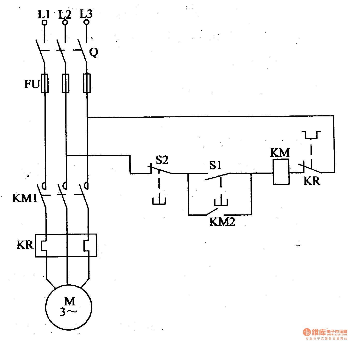
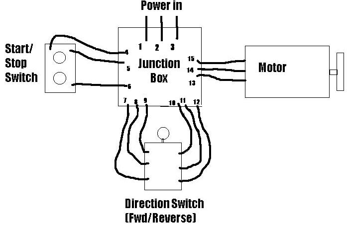
The most common use of 3 wire control is a startstop control. The following diagram is shown for 3 phase motor control of a delta star connection.

Xt 3710 Start Stop Motor Control Circuit Diagram Together
Start stop motor control wiring diagram. Single station with the starter. See image below for an example of 3 wire control being used to pull in a contactor to start a 3 phase motor. Two wire control two wire control as seen in configuration 1 consists of a control device containing one set of contacts used to facilitate the on an off operation of a pilot device. See image below for an example of 3 wire control being used to pull in a contactor to start a 3 phase motor. Pilot light l2 4 2 3 pilot light start stop bulletin 1495 normally closed auxiliary contacts are required. They are used in applications which do not require undervoltage protection.
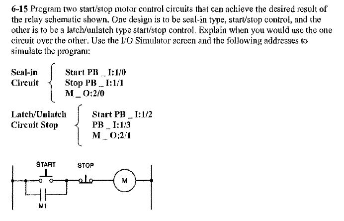
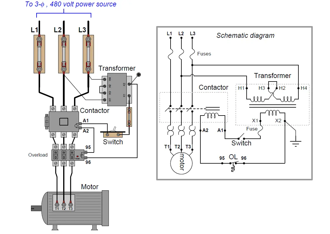
Star delta y δ 3 phase motor starting method by automatic star delta starter with timer. Start stop control wiring diagrams. Emolatur is offline push button for stop. One relay for control and the motor. Three phase motor connection schematic power and control wiring installation diagrams. When you press the start button and the stop button is not pressed the 24vdc relay energizes and it pulls in the r1 contactor that feeds three phase power to the motor.
It uses three contactors an overload relay one auxiliary contact block a normally open start pushbutton a normally closed stop pushbutton an on delay timer of 0 20 seconds and a power supply with a fuse. T w 6. Pressing start immediately sends power through the start pushbutton and the seal in contacting energizing the coil. Typical wiring diagrams for push button control stations 7 start stop control wiring diagrams single station with motor stopped pilot light l1 start l2 i 1 stop 2 oi 3 n wol. Wiring diagrams bulletin 609 manual starters are operated by start stop push buttons mounted on the front of the starter. The basic control circuits include two wire three wire controls manual automatic sequential control stopstart forward reverse and jogging circuits.
When you press the start button and the stop button. Wiring diagrams do not show the operating mechanism since it is not electrically controlled. C i m nc. Three phase motor connection stardelta without timer power control diagrams. With the switch closed the control circuit acts as a normal stopstart station controlling a load connected to the pilot device power is sitting on the start and seal in terminals of the pushbutton.


