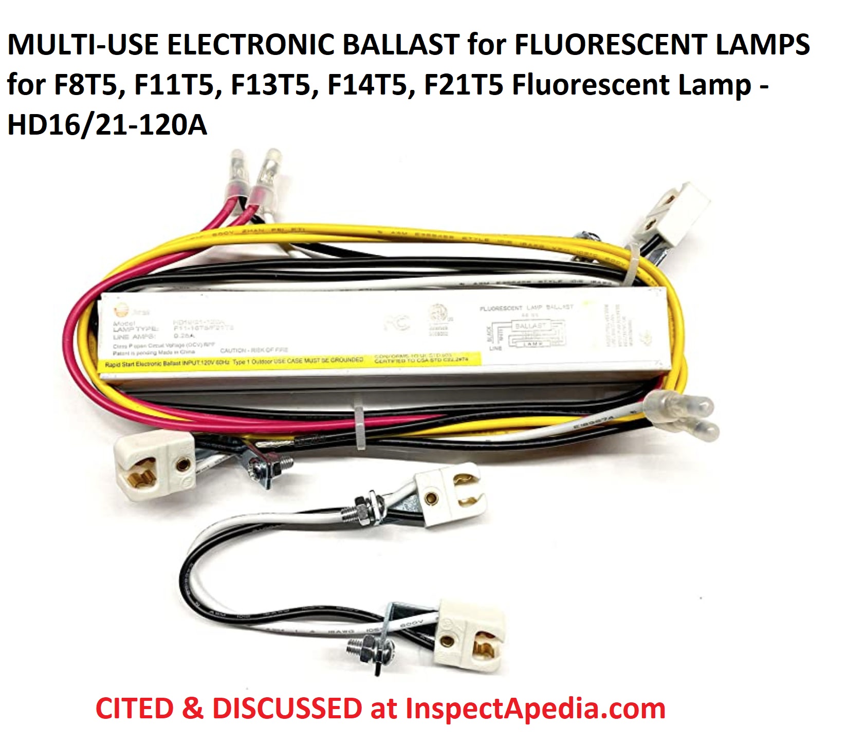
It really is intended to help all the typical person in creating a correct system. The technical guide will review the basics of fluorescent lamps and dimming ballasts including functional principles lamp varieties ballast factor and lifetime expectations.

Step Dimming Wiring Diagram Kuiyt 04alucard Seblock De
Step dimming ballast wiring diagram. Input power w thd at max. Easily monitor control and optimize a lutron control system from any tablet pc or smartphone. 0 10 dimming ballast wiring diagram wiring diagram 0 10 volt dimming wiring diagram. Load surge protection ring wave kv. C input current a max. The levelpro family of ballasts is designed for maximum energy savings and high efficiency and they are cee compliant.
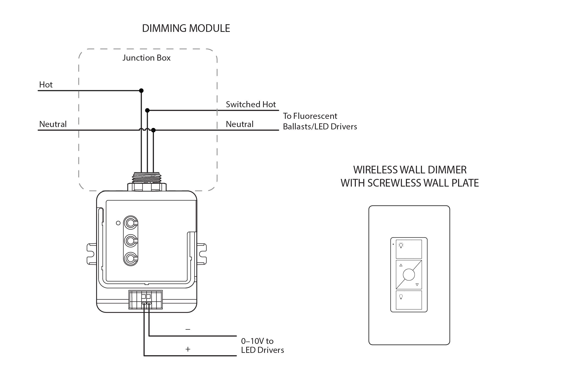
Enclosure wiring diagram 54w 01 15a 54v step dimming int with simpleset xi054c150v054sst1 input voltage vac output power w output voltage v output current a efficiency at 357v and 70c case max. The maximum bulb wattage is determined by the efficiency of the ballast. Groups of fixtures are connected to the control circuit to receive the same command signal thus the control can extend beyond a single power circuit layout. 0 10v dimming wiring diagram 0 10v dimmer switch leviton ip710 lfz or equal for other types of dimming control systems consult controls manufacturer for wiring instructions switched hot black switched hot red typical low voltage dimming wires purple gray typical electrical panel hot black typical 120v or 277v 60 hz neutral white. Load power factor at max. High ballast factor 118 to low 71 step dimming 100 light level of a 2 high ballast factor is approximately the same as a 3 lamp normal ballast factor 100 light level of a 3 high ballast factor is approximately the same as a 4 lamp normal ballast factor multi volt 120 277v flexibility.
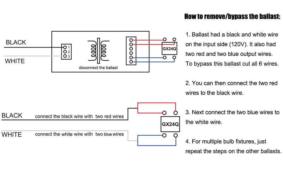
0 10 volt dimming wiring diagram wiring diagram 0 10 volt dimming wiring diagram. Consider 80 efficient as. These instructions will likely be easy to comprehend and use. The maximum number of ballast per dimmer is based on the load va rating. Installation topics such as ballast mounting grounding lamp mounting height wiring. Wiring diagram arrives with several easy to follow wiring diagram guidelines.
Step 3 step 4a single pole wiring application. This guide even contains suggestions for extra materials that you may want as a way to finish your tasks. Step dimming control facilitates energy code compliance without installation of low voltage control wiring. Lutrons new facility management tool empowers you to manage your building from anywhere. Of lutron fluorescent dimming systems. Maximum bulb wattage 0 10vdc ballasts are rated in volt amps va.
Dimming ballast designs differ from one manufacturer to the next so the number of lamps allowed on a lighting branch circuit may depend on a particular ballast type. These ballasts use two line voltage switches for selecting operation at full intensity or at half power. Wiring diagram also gives beneficial suggestions for tasks that may need some extra equipment. Ballast efficiencies will vary from different manufacturers.


