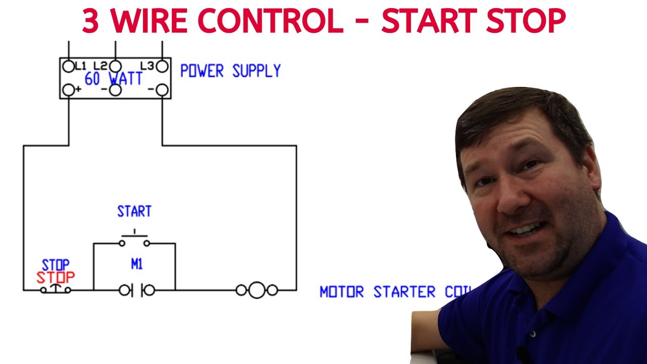
Motor control circuits are effective way to reduce cost by using smaller wire. See image below for an example of 3 wire control being used to pull in a contactor to start a 3 phase motor.

Practical Machinist Largest Manufacturing Technology Forum
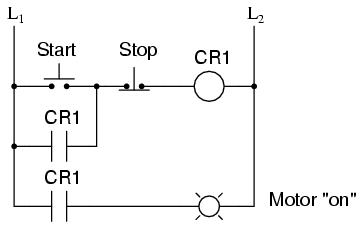
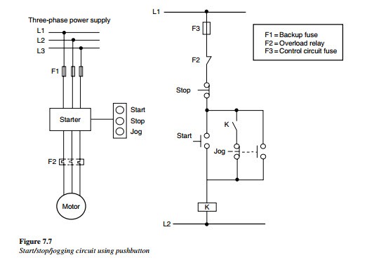
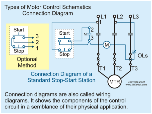
Stop start motor control circuit diagram. Depressing the stop button breaks the circuit de energizing. Often a hand drawn diagram of a control circuit con structed in the field helps in understanding how a circuit functions and how to make the necessary connections especially during the learning process. I am here with giving you a vfd start stop wiring diagram for running a vfd through panel board push button and keypad of the vfd it is called hmi. This means the control circuit is designed so there is no way for the load to become energized and stay energized through the memoryseal in contact. The most simple solution to this problem is the simple time proven run stop relay circuit. With this control circuit motion cannot commence or restart without the operators specific pushbutton command.
A three wire control circuit uses momentary contact startstop stations and a normally open seal in contact connected in parallel with the start button to maintain. Notice that the stop. I zl ii i i ii i i fo 0. Start stop control wiring diagrams single station basic circuit r 1 klai. I operation depressing the start button energizes coil m hold in contacts m and maintains the circuit after the start button is released. 1 j start 2 3 stop i no.
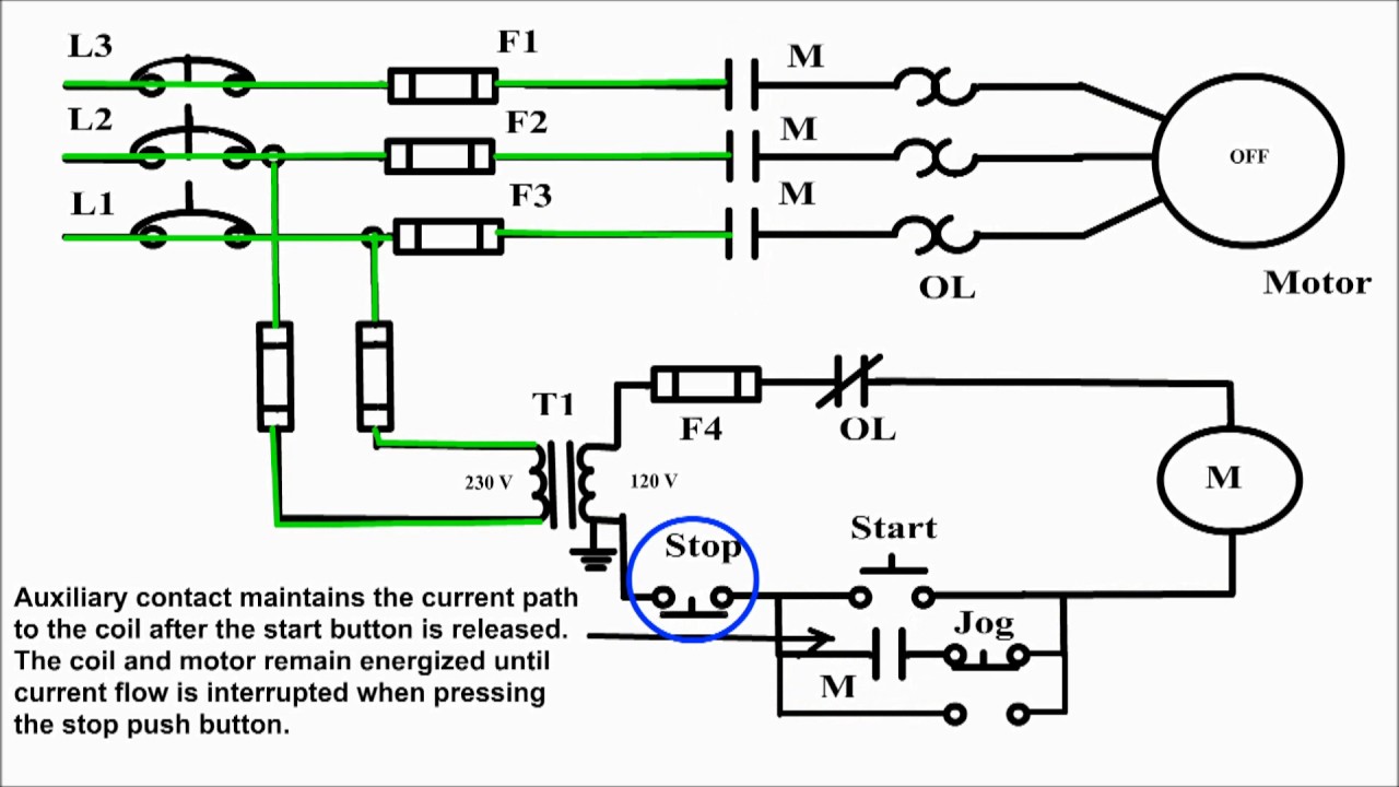
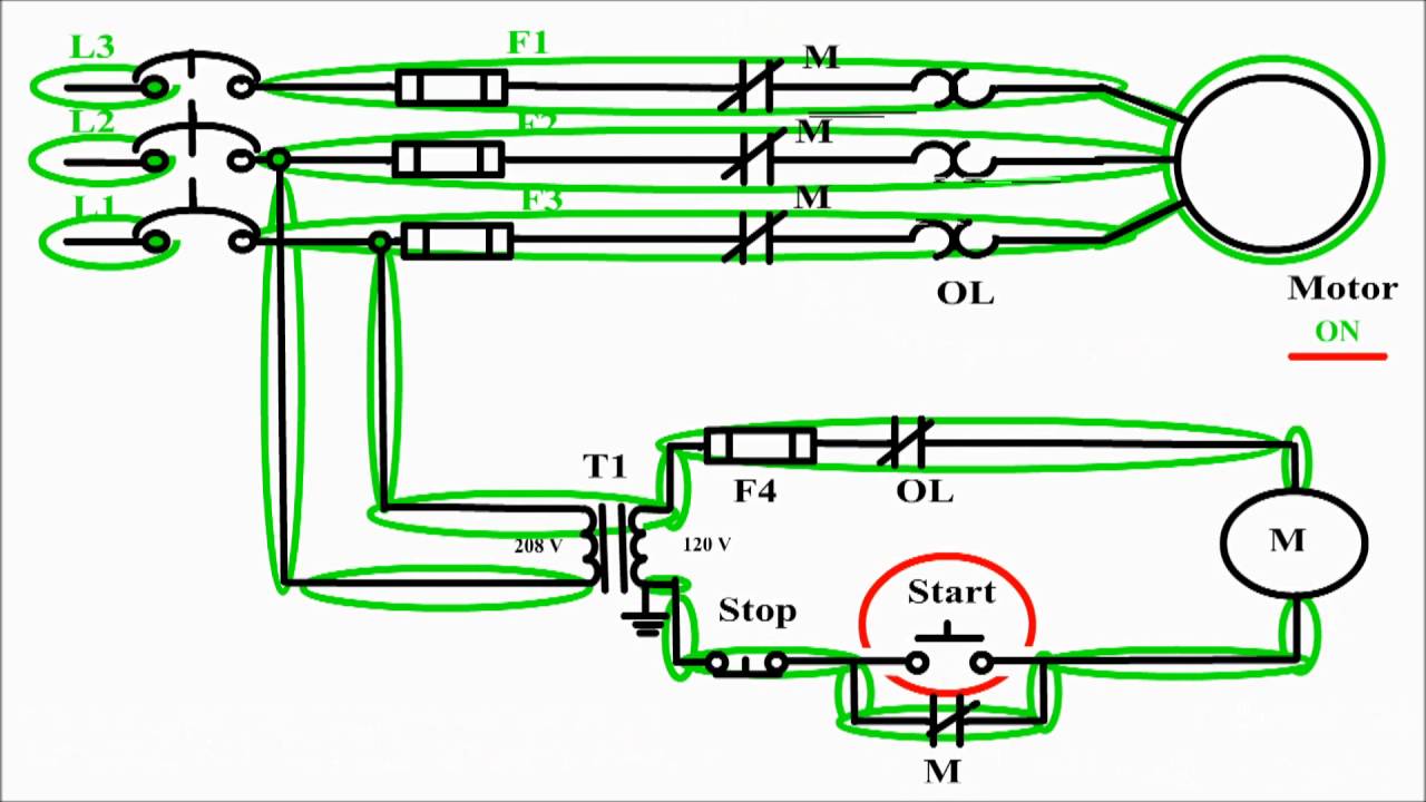
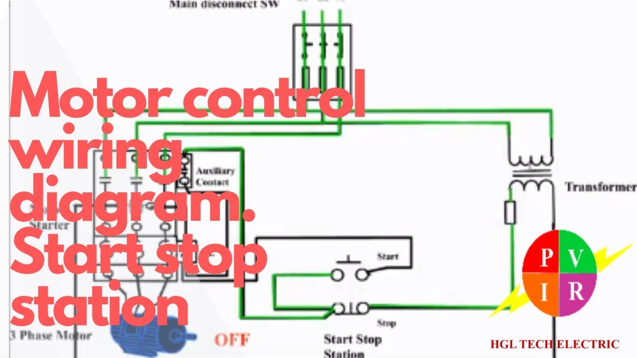
A very common form of latch circuit is the simple start stop relay circuit used for motor controls whereby a pair of momentary contact pushbutton switches control the operation of an electric motor. Vfd start stop wiring diagram. In this video i demonstrate a 3 wire startstop circuit. The basic operation of the stopstart circuit is to provide a means of remotely controlling a motor operated load from a panel that only contains the low voltage control circuitry. In this particular case i show a low voltage control circuit and a 3 phase higher voltage motor. One of the jog circuit designs is the two circuit pushbutton.
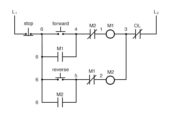
In such cases unwanted or unexpected motion is a risk to life or limb. This video guides you how the stopstart motor control circuits wiring done. Pressing the jog button creates a. The most common use of 3 wire control is a startstop control. Theres a diagram shown in the process. Figure 19 shows the hand drawn version of the 3 wire start stop control circuit shown in figure 13.
The circuit will operate as a normal three wire circuit if the start stop pushbuttons are used. I describe each of the components involved such as the motor starter overload start pushbutton stop pushbutton and control power and. When you press the start button and the stop button is not pressed the 24vdc relay energizes and it pulls in the r1 contactor that feeds three phase power to the motor. Vfd is a short form of variable frequency drive or variable voltage variable frequency drivethe vfds are working based on changing the input frequency and input voltage of the motor we can change the speed of the.
Gallery of Stop Start Motor Control Circuit Diagram