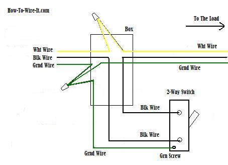
This diagram illustrates the wiring for a split half outlet controlled with a switch loop. The 2011 nec code requires that the switch loop use wires of the proper color code to signify hot wires.

What Is A Switch Loop Amp How Does It Work
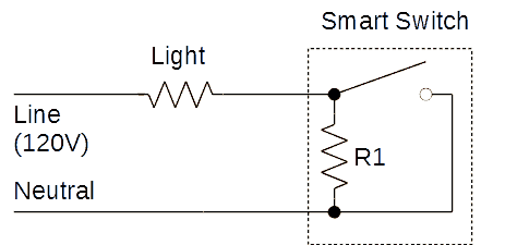
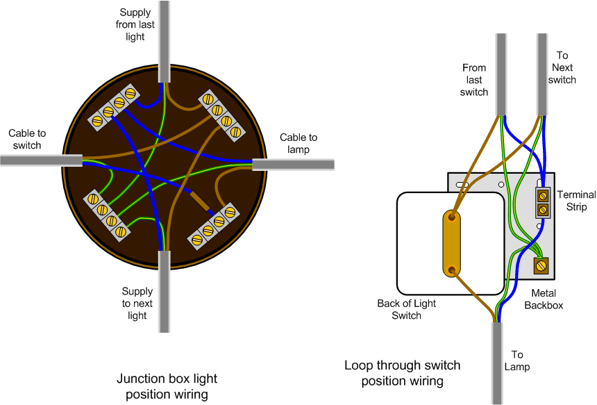
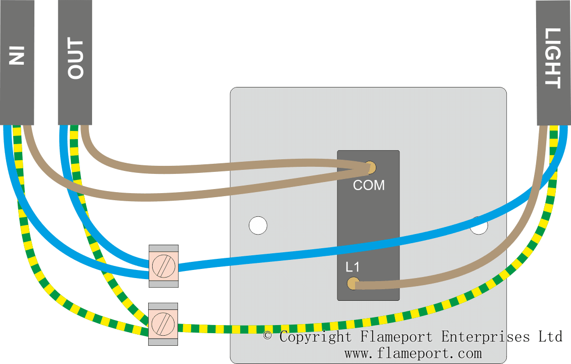
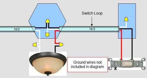
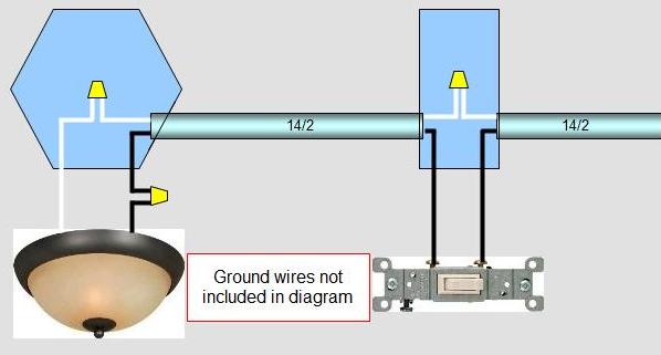
Switch loop wiring diagram. A switch loop occurs when both the switch at the end of a circuit or an incoming cable and a neutral become hot leads and connect to a terminal. This diagram illustrates wiring for one switch to control 2 or more lights. The tab connecting the hot terminals on the receptacle is removed and the source hot is connected to the bottom half. Wiring a split switched outlet with a switch loop. The source is at sw1 and 2 wire cable runs from there to the fixtures. In a switch loop the hot and neutral wires arrive at the light fixture before reaching the switch.
How does electrical switch wiring work. Bib jun 1 15 at 1238 1 if you are working on an older home with unmarked switch loops when you trace them also mark the white wires that should be marked so that they are marked for the next. The source neutral is connected to one of the neutral terminals on the receptacle. A white wire signifies a neutral wire. Figure 2 diagram of a switch loop. From a physical wiring standpoint it will be necessary at a minimum to run 143 cable which contains a black red and white wire.
Multiple light wiring diagram. For new wiring you would run a three wire cable and use the red and black for the loop and leave the white unused and capped in the switch box. The hot and neutral terminals on each fixture are spliced with a pigtail to the circuit wires which then continue on to the next light.


