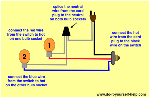
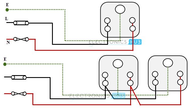
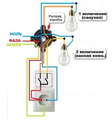
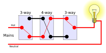
To wire multiple outlets follow the circuit diagrams posted in this article. The hot source wire is removed from the receptacle and spliced to the red wire running to the switch.

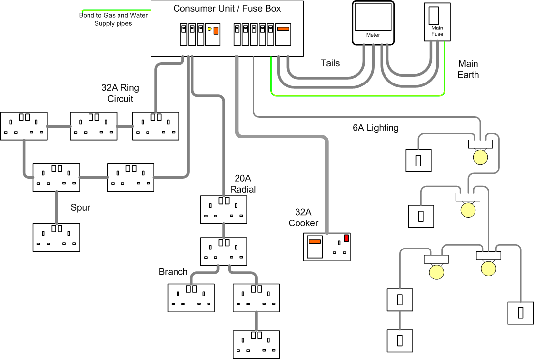
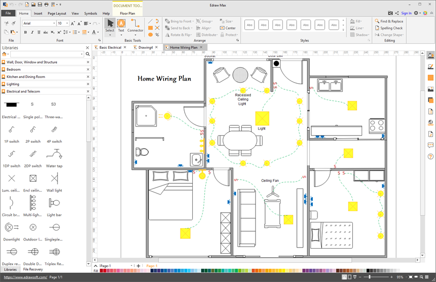
Electrical Installations Electrical Layout Plan For A
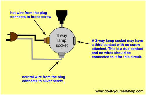
Switch socket wiring diagram. The threaded socket is the neutral. This wiring diagram illustrates adding wiring for a light switch to control an existing wall outlet. The black wire from the switch connects to the hot on the receptacle. This is a wiring diagram for a standard 3 way lamp switch. The socket is used with a three way bulb containing 2 separate elements that are energized separately and then together as the switch knob is turned for varying degrees of light. Wiring a 3 way lamp socket switch.
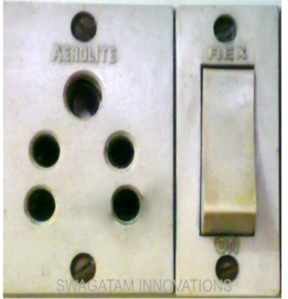
These sockets have two terminals one for the hot wire and one for the neutral. The source is at the outlet and a switch loop is added to a new switch. The socket receptacles are usually marked with signs to indicate the position that each wire should go. So when the switch is off all hot parts of the lamp are well protected. And when the switch is on only the tab at the bottom of the socket is hot but if the wiring is reversed and the power goes to the threaded socket the threaded socket is always hot whether the switch is on or off. Electric board wiring connection socket switch indicator lampfusefan pointlighting point 8 way board connection diagram link httpsdrivegooglec.
This article explains a 3 way switch wiring diagram and step how to wire three way light switch electrical circuit we have to discuss. Explanation of wiring diagram 1 switch wiring shows the power source power in starts at the switch box. Circuit electrical wiring enters the switch box the black wire power in source attaches to one of the switch screw terminals.

