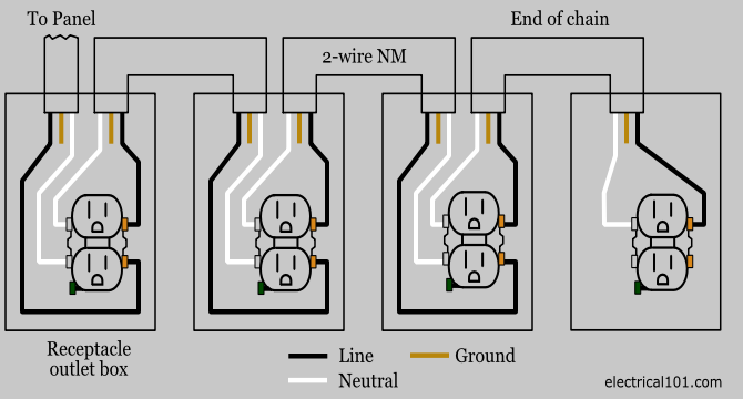
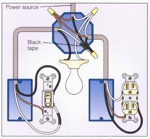
Also shown is the half of the receptacle that is live at all times and the tab that must be cut in order to split the receptacles. The source neutral is connected the line neutral terminal.

Leviton Combination Switch Wiring Diagram Wiring Diagrams
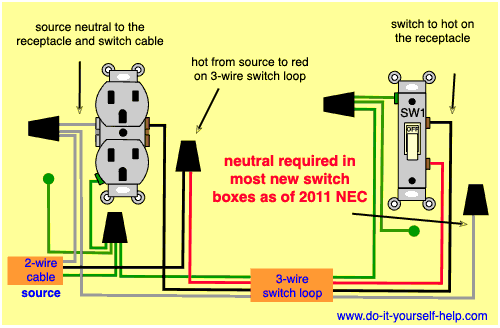
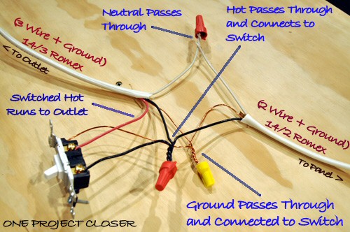
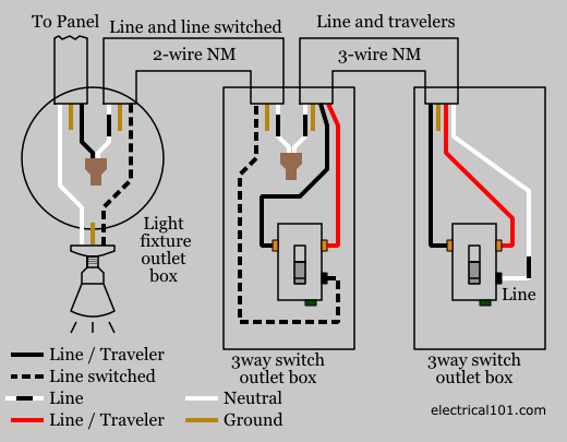
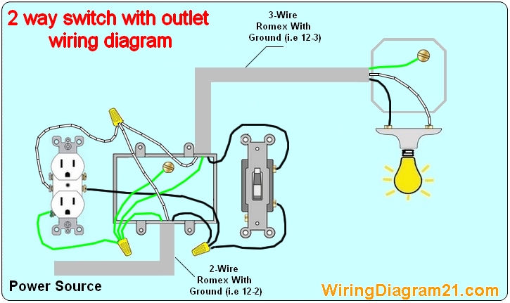
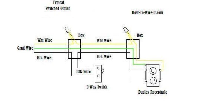
Switched outlet wiring diagram. Switched split outlet wiring diagram for controlling the half of two duplex electrical receptacles by a wall switch without a neutral conductor. Connect the last switch in the usual manner looping the wire around the screw in a clockwise direction. At the outlets each is wired using a pigtail splice to make the hot and neutral connections. The diagram below shows the power entering the circuit at the grounded outlet box location then sending power up to the switch and a switched leg back down to the outlet. Three wire cable runs between the switches and the outlet. This circuit is wired the same way as the 3 way lights at this link.
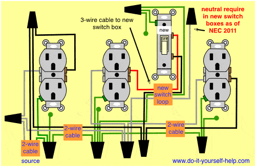
The source for the circuit is at the switch and 2 wire cable runs to each receptacle outlet. This diagram shows the wiring for multiple switched outlets on one switch. In this diagram two 3 way switches control a wall receptacle outlet that may be used to control a lamp from two entrances to a room. Instead of running a separate pigtail from the hot wire to each switch just leave the hot wire extra long. My light switch wiring diagrams may be helpful to you. In this diagram the switch built into the combo device is wired to control the gfci outlet itself.
The source hot wire is spliced with one of the switch wires and the other switch wire is connected to the hot line terminal on the device. To connect the switches simply score the wire with your wire stripper and push the insulation to expose about 34 in. 3 way switched outlet wiring. Wiring diagram for a switched gfci combo outlet. Wiring diagram for multiple switched outlets. These electrical wiring diagrams show typical connections.


