Tekonsha brake controller wiring diagram wiring diagram for trailer brake controller best tekonsha voyager wiring diagram for trailer brake controller 9030. A wiring diagram is a streamlined standard pictorial depiction of an electrical circuit.

Land Roverlander 1 Wiring Diagram Diagram Base Website Wiring
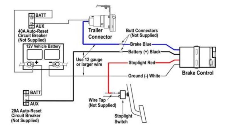
Tekonsha voyager wiring diagram 9030. It is compact size and features like a bicolored led brake monitor to assure a complete connection to trailer brakes and give an indication of relative braking power being applied make the voyager extremely versatile. See below failure to install brake control within these constraints may cause your control to become inoperable. See below failure to install brake control within these constraints may cause your control to become inoperable. Wiring diagram tekonsha voyager brake controller 39510. The red wire must tap into the cold side of your vehicle brakes. Each part should be set and connected with other parts in particular way.
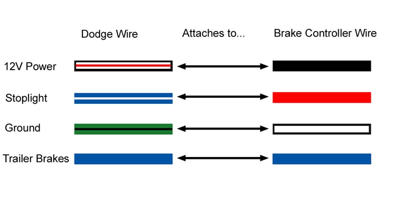
6 x 38 screws. It is compact size and features like a bicolored led brake monitor to assure a complete connection to trailer brakes and give an indication of relative braking power being applied make the voyager. Yes we can help. The voyager incorporates patented braking sensor by tekonsha and is the best value you will find for smooth and secure trailer braking. They should be white blue red and black. Otherwise the structure wont function as it should be.
The voyager incorporates patented braking sensor by tekonsha and is the best value you will find for smooth and secure trailer braking. Collection of tekonsha brake controller wiring diagram. Tekonsha voyager wiring diagram tekonsha voyager electric brake controller wiring diagram tekonsha voyager installation instructions tekonsha voyager wiring diagram every electric structure is made up of various distinct components. You should have four wires coming out of the back of your tekonsha 9030 voyager brake activator part 39510. Assortment of tekonsha voyager wiring diagram. Tekonsha voyager 9030 minimizes interference with tow vehicle electrical systems uses a four wire hook up has a broad setting range and is compatible with most any vehicle.
Below you will find a link to the installation instructions. Traditional bracket mount a. Is it possible to get the wiring diagram for this controller. 6 x 38 screws 1. The white wire is grounded. Wiring diagram pics detail.
It shows the parts of the circuit as simplified shapes and the power and signal links in between the gadgets. To the right there is a picture that has a diagram of how most brake controllers wire up if you click it you will be able to see an enlarged version of the picture. Warning the brake control must be mount ed from 20 degrees nose down to 70 degrees nose up.


