The ratio arms r1 and r2 of the bridge are kept fixed say unity. Real time temperature is displayed on its lcd screen and you can use it to control the temperature within the preset minimum and maximum range.
T 121 Temperature Sensors Form A Temperature Control Circuit
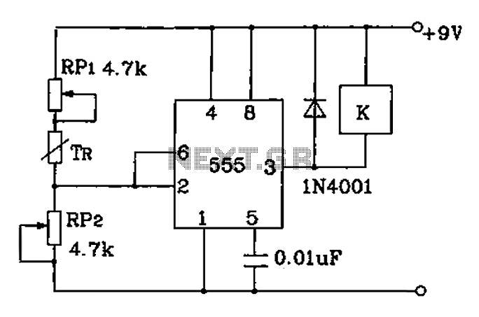
Temperature control circuit diagram. 2 shows circuit diagram of the digital temperature controller. The controller has been designed and fabricated using the op amp ic 741 and a 1k thermistor as the temperature sensor. The diy temperature controller circuit presented in this article is super simple in design yet is able to produce reasonably accurate and consistent temperature control over a range of 40 to 125 degrees celsius which is fully adjustable. When the thermistor temperature is below a set value the voltage at pin 2 of the 555 drops below 13 of vcc. Temperature control system circuit. For example it can use for temperature control of an incubator where maintaining a precise temperature is very important.
Digital temperature controller circuit and working fig. This turns on the triac controlled heater and also starts the timing cycle. How does the temperature controller circuit works. This circuit is connected to the main 220v line therefore it must be handle only by experts. It is based on the principle of wheatstone bridge. Figure 914 shows a start stop push button circuit.
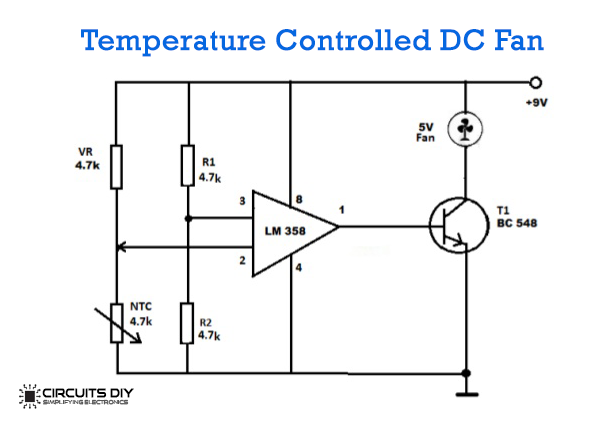
A digital temperature controller circuit is a precise temperature controller in medical industrial and home applications. In the previous topics we have discussed the temperature circuits which are based on transistors like temperature alarm circuit. It works on the principle of thermistor. Working of temperature controlled dc fan using thermistor. The circuit can be used to control any ac or dc device on the desired temperature. We commonly use temperature control systems in air conditioners refrigerators geysers etc.
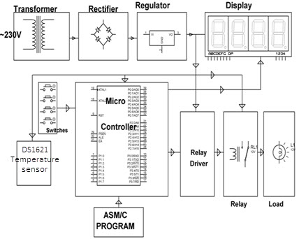
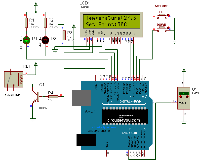
Schematic diagrams do not always show both control and motor connections. A temperature controlled system is a type of control system that automatically controls the temperature of an object or an area. It comprises microcontroller atmega8535 temperature sensor lm35 regulator 7806 an lcd module and a few discrete components. This system is better than analoguethermostat system which has poor accuracy. Where the temperature is automatically adjusted as per the input settings. The first circuit to be discussed is a basic control circuit used throughout industry.
1 shows the circuit of the temperature control system. The 230v 50hz ac mains is stepped down by transformer x1 to deliver a secondary output of 9v 500 ma. In order to implement a temperature control system we need a. In this circuit pin 3 non inverting terminal of op amp 741 is connected with the potentiometer and pin 2 inverting terminal is connected in between of r2 and rt1 thermistor which is making a voltage divider circuit. Many schematic diagrams show only the control circuit. This schematic shows both the control circuit and the motor circuit.
Circuit diagram temperature control. The figure shows a very useful project of a temperature control circuit using 555 ic. The voltage across the thermistor ie.
Gallery of Temperature Control Circuit Diagram