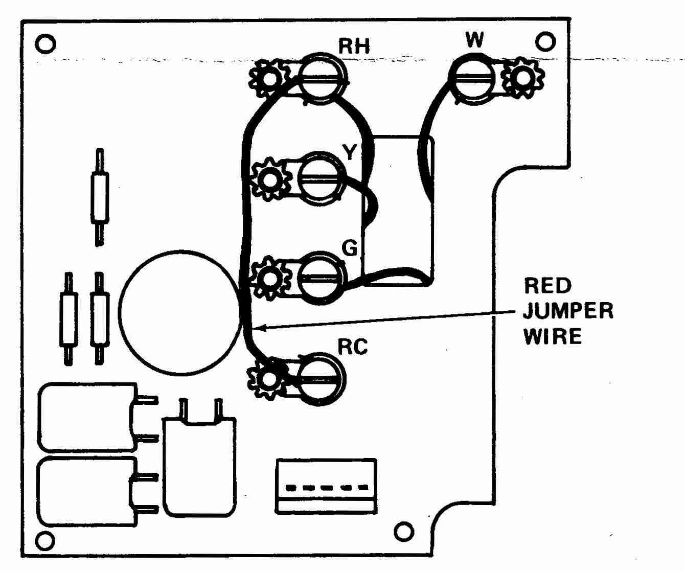
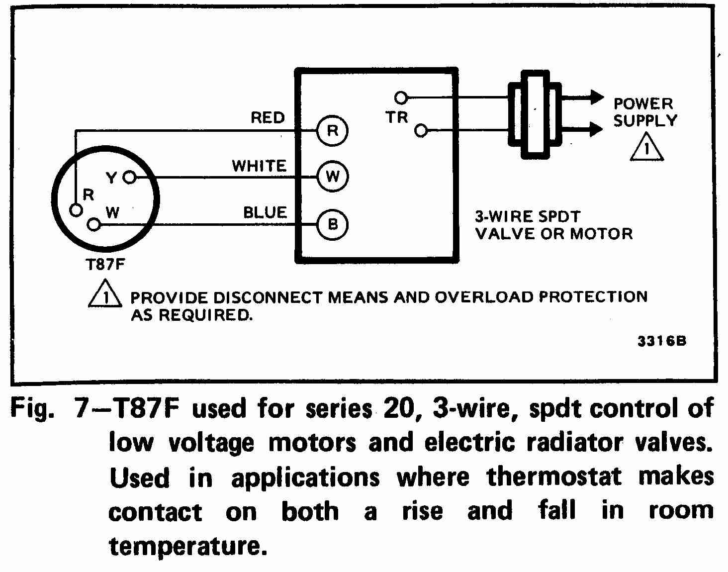
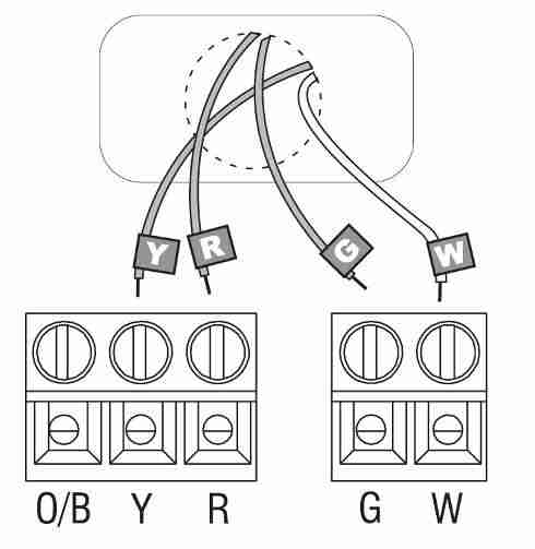
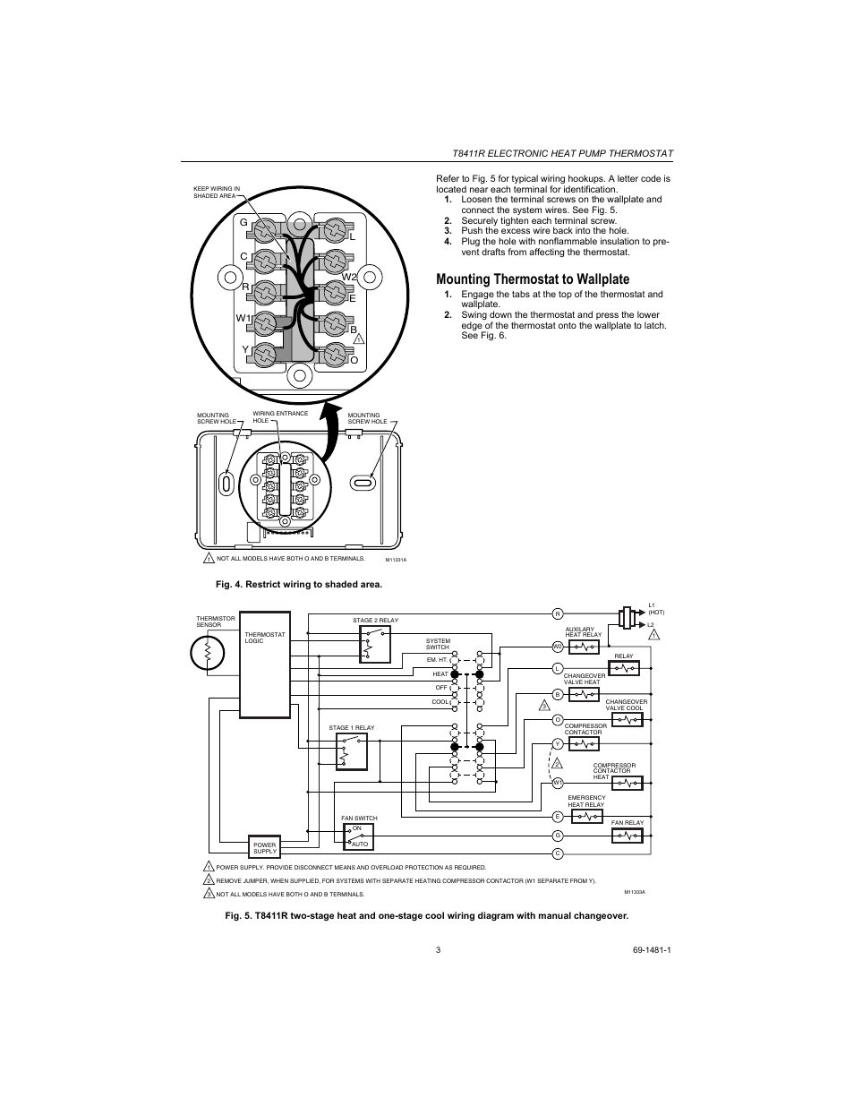
This diagram illustrates the wiring connections for a heat pump system with auxiliary heating. The color of wire r is usually red and c is black.
Th5220d1003 Wiring Diagram H1 Wiring Diagram
Thermostat wiring diagram for heat pump. A wiring diagram is a streamlined conventional photographic representation of an electrical circuit. C is known as the common terminal. Always follow manufacturers instructions for both the thermostat and the hvac system. Variety of honeywell heat pump thermostat wiring diagram. As shown in the diagram you will need to power up the thermostat and the 24v ac power is connected to the r and c terminals. Heat pump thermostat wiring a typical wire color and terminal diagram.
Heat pumps are different than air conditioners because a heat pump uses the process of refrigeration to heat and coolwhile an air conditioner uses the process of refrigeration to only cool the central air conditioner will usually be paired with a gas furnace an electric furnace or some other method of heating. Heat pump thermostat wiring chart diagram hvac the following graphics are meant as a guide only. W2 aux and or e emergency wiring connections will normally connect to the ecobee3 w1 terminal. It shows the parts of the circuit as simplified shapes and also the power as well as signal connections between the devices. Additional articles on this site concerning thermostats and wiring can help you solve your problem or correctly wire a new thermostat. Thermostat wiring diagrams for heat pumps heat pump thermostat wire diagrams.
Ecobee3 manages auxiliary heating through the w1 w2 if there is more than 1 stage of aux heat terminals outputs. These two connections will ensure that there is power to the thermostat that you are operating.


