Busbars carries this three phase power and from which individual connections are brought out to individual loads through cables. Three phase wiring diagrams always use wiring diagram supplied on motor nameplate colored leads are only applicable on the new rolled steel motor lines single phase wiring diagrams always use wiring diagram supplied on motor nameplate for motors with thermal protection.

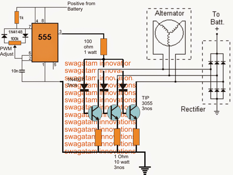
Podtronics Instructions Burton Bike Bits
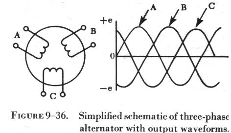
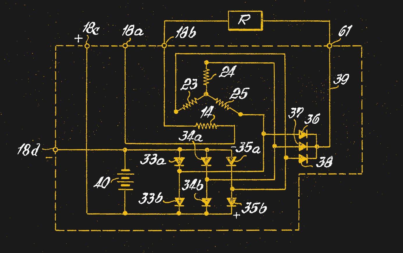
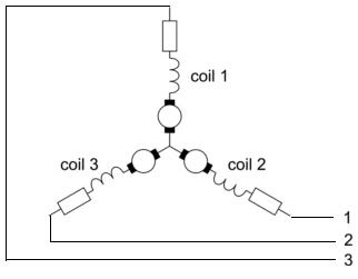
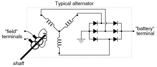
Three phase alternator wiring diagram. A wiring diagram is a simplified traditional pictorial depiction of an electric circuit. The figure below shows schematic diagram for industrial three phase wiring. A schematic diagram of a three phase stator showing all the coils becomes complex and it is difficult to see what is actually happening. It shows the parts of the circuit as streamlined forms and also the power as well as signal links in between the gadgets. The three phase alternator as the name implies has three single phase windings spaced such that the voltage induced in any one phase is displaced by 120 from the other two. The three phase alternator as the name implies has three single phase windings spaced such that the voltage induced in any one phase is displaced by 120º from the other two.
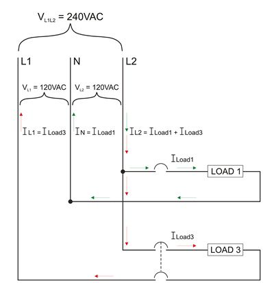
With single phase the magnets and coils all line up with each other and are said to be in phase. The simplified schematic of figure 3 8 view a shows all the windings of each. The diagram below shows single phase wiring. Three phase power from the utilities is connected to the main breaker through three phase energy meter. A schematic diagram of a three phase stator showing all the coils becomes complex and it is difficult to see what is actually happening. In a single phase unit the coils are wound opposite of the first.
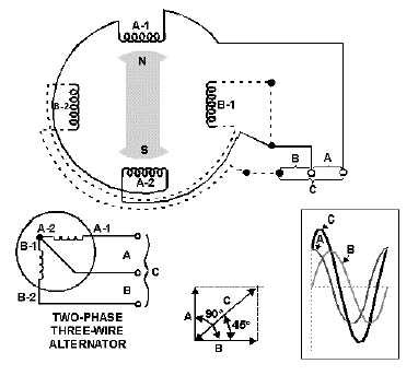
Collection of three wire alternator wiring diagram. Basically phase relates to the timing of the magnets passing over the coils at different times.
