4 way switch configurations are used to control lights with three or more switchesa 3 way switch is used on each end with one or more 4 way switches in between the two 3 way switchesthey do not have an onoff position like single pole switches. It is important to understand how these switches are wired before attempting to troubleshoot or replace.

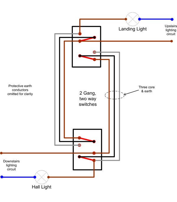
Lighting Circuit Diagrams For 1 2 And 3 Way Switching
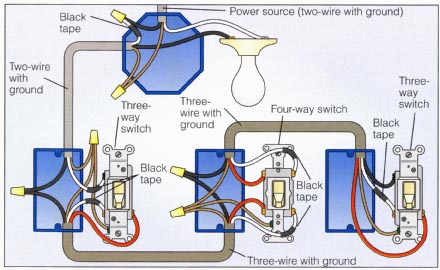
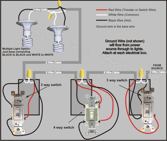
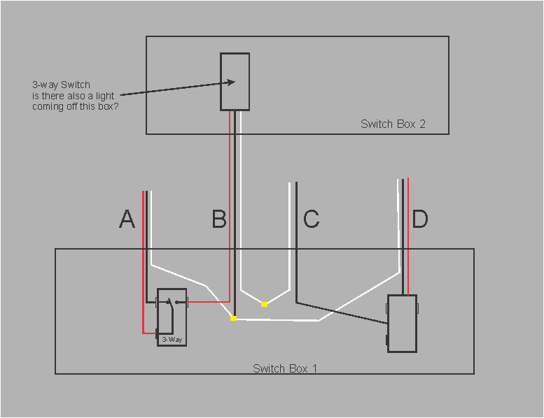
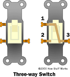
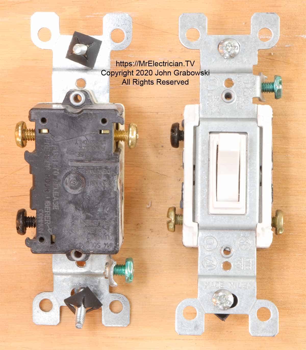
Three way switch internal diagram. See alternate 3 way switch wiring configuration for another way 3 way switches may be wired. With these diagrams below it will take the guess work out of wiring. Each component should be set and connected with other parts in specific manner. Check here for 4 way switch troubleshooting and help with 3 ways switches here. The center switch is 4 way switch while the outer two switches are 3 way. This might seem intimidating but it does not have to be.
That page and its links also discuss proper wire colors and several wiring alternatives. Ceiling fan 3 way switch wiring diagram ceiling fan 3 way switch wiring diagram hunter ceiling fan 3 way switch wiring diagram every electric arrangement consists of various diverse components. Wiring diagram 3 way switch with light at the end. Included are a 4 way dimmer switch diagram and an arrangement that can be used to control room lights from four different locations. If you have any problems with these switches it may be best to call an electrician. If not the structure will not function as it should be.
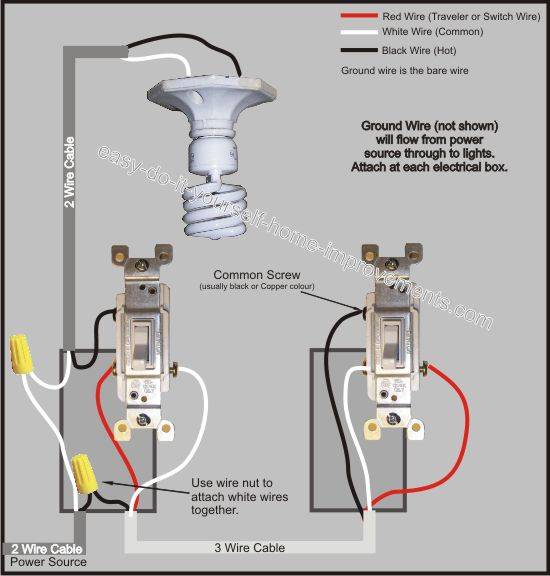
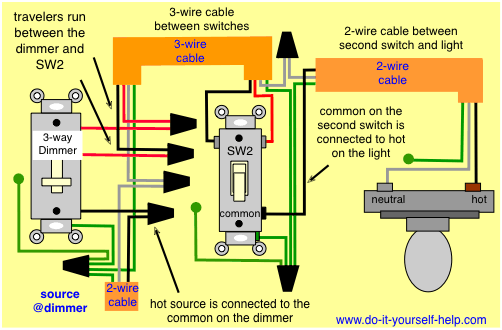
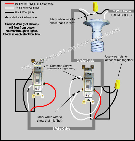
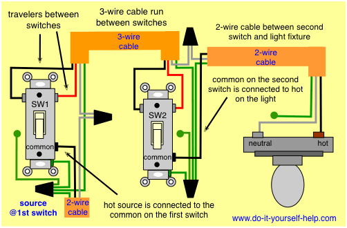
This wire diagram shows the wiring for source power into the first three way switch then 3 wire cable to the next 3 way light switch and then on to the light or light fixtures. The basic 3 way switch wiring diagram this is the most common and the easiest wiring diagram to follow of any of the wiring diagrams for a 3 way switch circuit. Important note about your safety. For a discussion of how to wire such circuits see 3 way and 4 way light switches. In this diagram the electrical source is at the first switch and the light is located at the end of the circuit. Most common is the single pole switch the type used to control a light fixture from a single locationthe next most common is the three way switch which is commonly used to control a light fixture from two different locations.
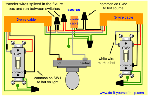
For circuits that control lights from two locations only check the wiring diagrams at this link. Pick the diagram that is most like the scenario you are in and see if you can wire your switch. Wiring a 4 way switch with light at. 3 way switch wiring diagram. If you intend to add multiple lights with a 3 way switch use the 3 way switch for multiple lights diagram. Unfortunately not all 3 way switches are wired the conventional way.
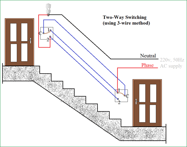
For example a long hallway or stairway might use a pair of three way. Before you grab your toolbox and set out to wire a three way switch wire a ceiling fan or any other electrical work be sure to take proper safety precautions. Three wire cable runs between the switches and 2 wire cable runs to the light. Shown above is an animation of a circuit using three switches to control a light. The diagrams below show the conventional wiring for 3 way switches. The black and red wires between sw1 and sw2 are connected to the traveler terminals.
Wall switches used to control ceiling light fixtures or other fixtures come in three types. Take a closer look at a 3 way switch wiring diagram.
