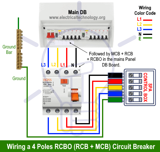
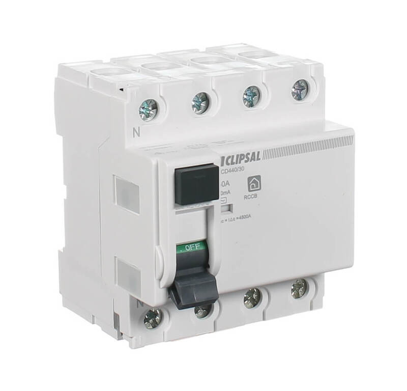
Wiring a four poles rcbo or gfci circuit breaker three phase rccb wiring the three phase wiring for gfci or rcd rccb or rcbo wiring diagram shows the three lines l1 l2 and l3 and neutral has been connected as input to the rccb from main board followed by mcb ie. Demand of these three circuits must not exceed rating of rcd ol n n n a neutral link do not earth ol clipsal rcd 2 4n 1 3n a mains switch a e n n an.

Three Phase Electrical Wiring Installation In Home Nec
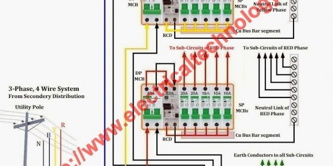
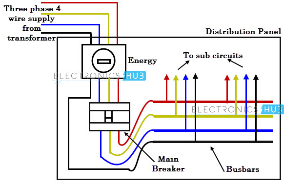
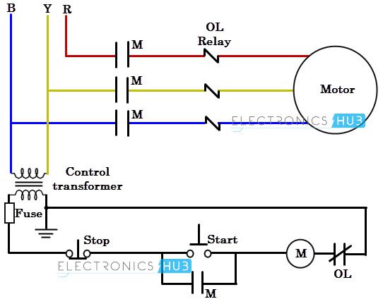
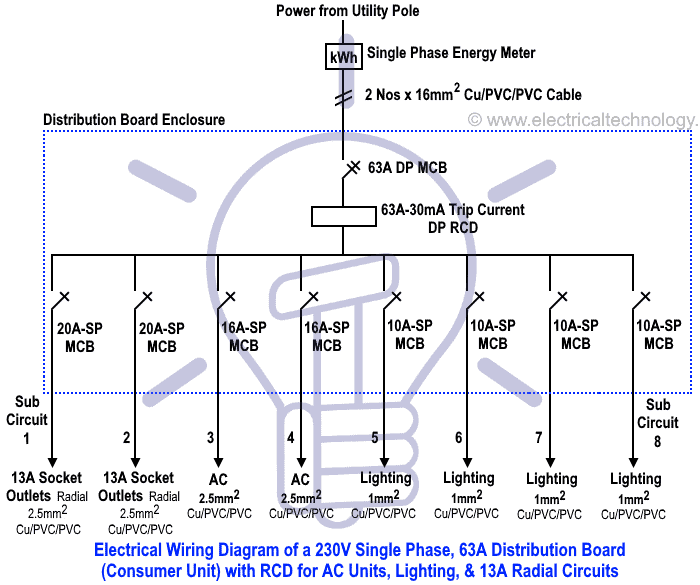
Three phase rcd wiring diagram. In the above figure power from the utility pole is connected to sub circuits via three phase energy meter three phase breaker 3 pole 60a double pole rcd double pole mcb and single pole mcbs. In our today electrical wiring installation tutorial we will show how to do a three phase consumer unit installation from utility pole to a 3 phase energy meter 3 phase distribution board and then how to connect single phase three phase loads in a three phase wiring distribution system in home electric supply system. Rcd wiring installation in single phase distribution board the wiring installation of rcd is very simple in main distribution board you need to connect the fixed rcd after the. Rcd are available in many types but fixed rcd residual current device are number one device to make a great protection in electrical single phase wiring installation. The figure below shows schematic diagram for industrial three phase wiring. The first step is to figure out the voltage of your phases.
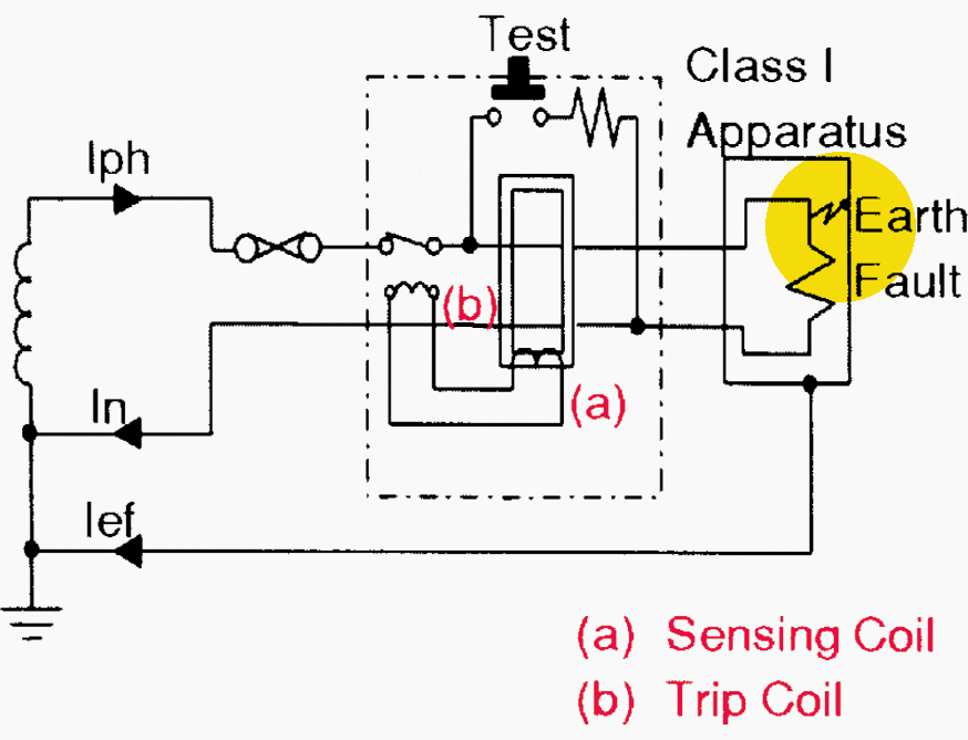
These are 3 phase devices and the rcd is an add on module which can only be used with the matching. Singele phase db wiring diagram single phase meter wiring diagram energy meter and mcb board. A defective merlin gerin mcbrcd combination is totally dismantled to see what is inside. For wiring rcd four pole circuit breaker connect your incoming 3 phase 4 wire supply to the input connection of fixed rcd eg example connect neutral n and phases l1 l2 l3 to input terminals and then get supply form out terminals as shown in below diagram. That being said there is a wide range of different motors and what you have on hand can be completely different. Dual rcd consumer unit.
Clipsal rc and 4rc series residual current device wiring diagrams 1 2 main switch single phase e 3n 4n clipsal rcbm 4rcbm and 4rcbe series combined mcbrcd wiring diagram a warning combined max. A three phase motor must be wired based on the diagram on the faceplate. Three phase dol starter control overload indicator power wiring diagram. In the united states for low voltage motors below 600v you can expect either 230v or 460v.
