The above diagram shows you the pin numbering for both male and female xlr connectors from the front and the rear view. 3 phase 5 pin plug wiring diagram.
.jpg)
How To Control 3 Pin Socket By One Way Switch English Video
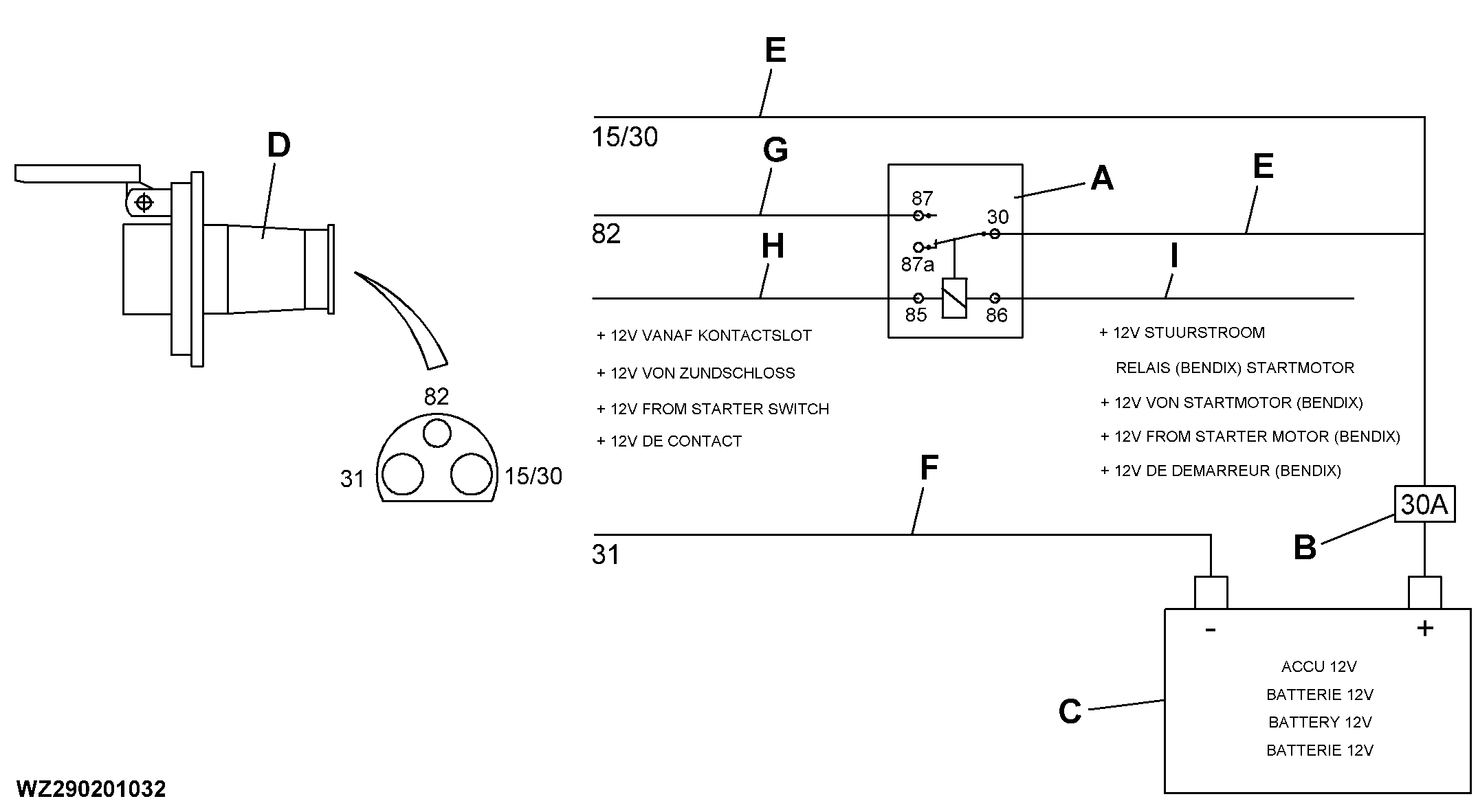
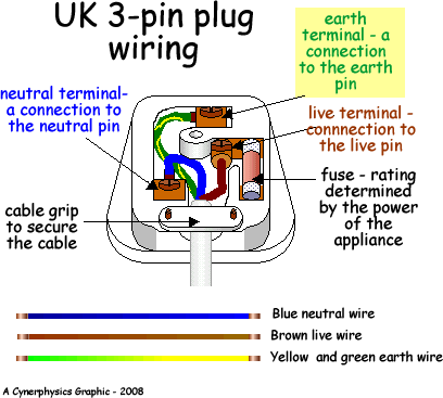
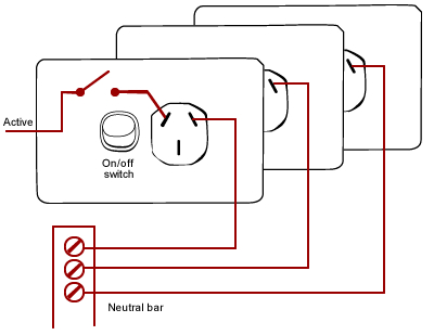
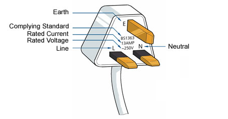
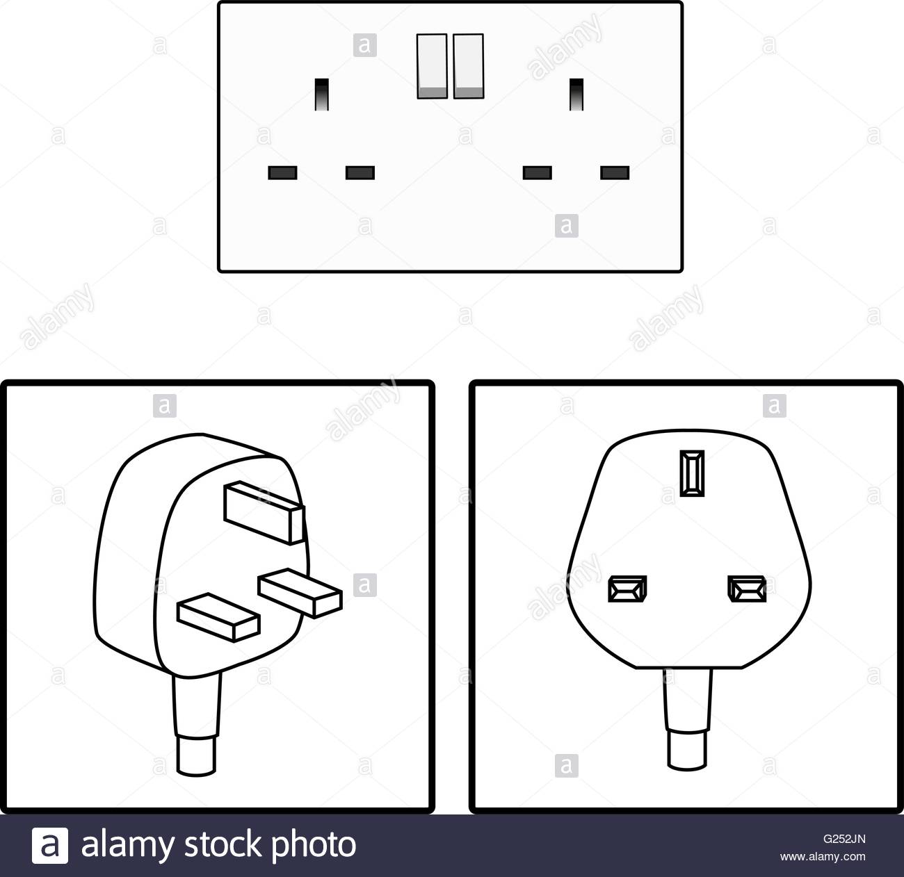
Three pin socket diagram. The rear view is the end you solder from here are the connections on each pin. Download 3 pin socket wiring diagram pdf. Proper fan connector placement is shown in the. Take the insulation wires and strip about inch on the ends. Download 3 pin socket wiring diagram free files. To wire a switched three pin socket first of all connect the earth wire to e connection of socket and then connect the neutral wire to n point of socket and connect the phase wire to circuit breaker and then connect a wire between circuit breaker output terminal and socket l or p terminal as show in below diagram.
4 pin connectors are usually used by cpu fans with higher power consumption. 3 pin xlr wiring standard 3 pin xlr connectors are standard amongst line level and mic level audio applications. Chassis and cpu fans may use either 3 pin or 4 pin power connectors. Diagrams of wired ring in socket information about pdf. How to wire up a 7 pin trailer plug or socket kt blog pdf. If you do not have any experience then watch my video and you can give three pin plug connection.
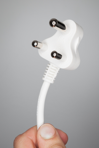
This video will show you how to put three pin plug connections. 3 pin connectors are usually used for the smaller chassis fans with lower power consumption. Fans and on board fan headers are backwards compatible. How to wiring the cable of 5p industrial sockets and plugs. 3 pin socket wiring diagram download read online.


