If you were under the impression that switches simply turn circuits on and off. Most electronic circuits contain an onoff switch.
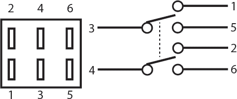
Understanding Toggle Switches
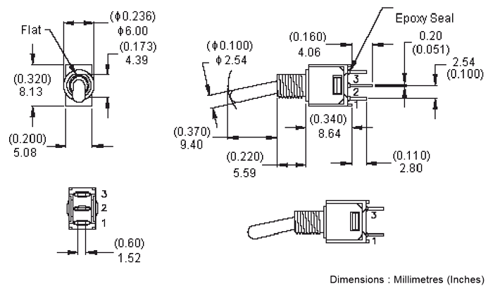
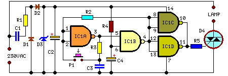
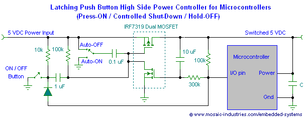
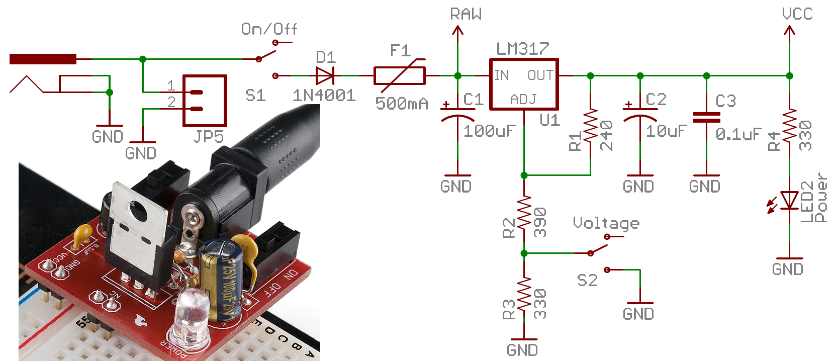
Toggle switch circuit diagram. It reveals the components of the circuit as simplified forms and also the power as well as signal links in between the devices. A spst toggle switch can act as a simple on off switch in a circuit. In addition to the onoff switch many circuits contain switches that control how the circuit works or activate different features of the circuit. The clock input pin 14 controls all the 10 outputs of the ic and activate each output on a single positive pulse. 3 position toggle switch wiring diagram 3 position toggle switch wiring diagram every electric arrangement is composed of various unique pieces. Each component ought to be set and linked to different parts in specific manner.
How to connect 2 way switch wiring using three wire control. But the reset pin is shorted with the q3 output pin 7 so that ic will toggle between q1 and q2 outputs. Where 0 represents the off condition and 1 represents the on condition. Usually the onoff switch will be maintained like a toggle or slide switch but momentary onoff switches can have their purpose. Its clock inhibit pin is grounded so that ic can run freely. While spdt and dpdt toggle switches can flip different devices on or off in a cirucit.
In the circuit ic cd 4017 is used in the toggle mode. One way to classify switches is by the connections they make. With a pair of 3 way switches either can make or break the connection that completes the circuit to the light. Assortment of on off on toggle switch wiring diagram. A wiring diagram is a streamlined standard photographic representation of an electrical circuit. Wiring a 3 way light switch.
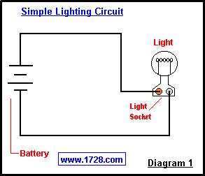
Spst toggle switch wiring. We have also used a rc circuit 22uf capacitor and 100k resistor at clock pin 14 of 4017 so that it only counts one clock pulse on each time button is pressed. In most circuits this work is done by a multivibrator circuit but in this project this ic is used as a simple toggle switch so the pin 13 is connected to the ground to freely run the ic and the pin 15 is connected with the 2nd output of the ic that is pin 4 to toggle the ic between. When the switch is closed current flows and the led can illuminate. This is the new method to make a 2 way switching connection as it is slightly different from the two wire control method. This method is commonly used now days as it is efficient than the two wire control system.
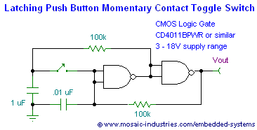
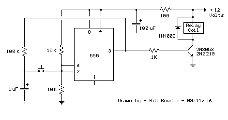
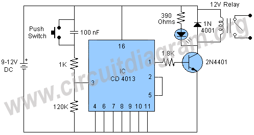
If not the structure will not work as it should be. This toggle action can be exploited in various relay driver circuits. A circuit diagram with an led resistor and a switch. We will now go over the wiring diagram of a spst toggle switch. Wiring a 3 way light switch is certainly more complicated than that of the more common single pole switch but you can figure it out if you follow our 3 way switch wiring diagram. Toggle switches are common components in many different types of electronic circuits.
Otherwise no current flows and the led receives no power. So it works like a toggle switch. Otherwise circuit may behave unexpectedly or it can count two or more pulses because of noise or bouncing effect of push button.


