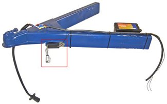
A wiring diagram is a streamlined conventional pictorial representation of an electric circuit. Mount the battery box inside the trailer frame in a protected location.
Trailer Kes Wiring Diagram Wiring Diagram Images
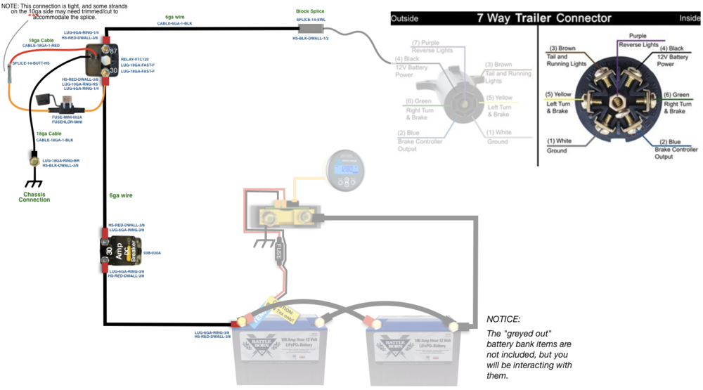
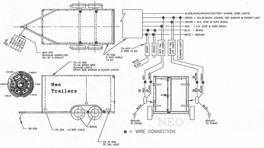
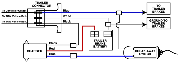
Trailer brake wiring diagram with battery. Wiring diagram also gives helpful recommendations for projects that may require some extra equipment. 4 way trailer connectors are typically used on small trailers such as boat snowmobile utility and other trailers that that do not use brakes. Trailer wiring diagrams trailer wiring connectors. Trailer wiring diagrams trailer wiring connectors various connectors are available from four to seven pins that allow for the transfer of power for the lighting as well as auxiliary functions such as an electric trailer brake controller backup lights or a 12v power supply for a winch or interior trailer lights. Install the mounting bolts diagonal from each other. If not the arrangement will not function as it ought to be.
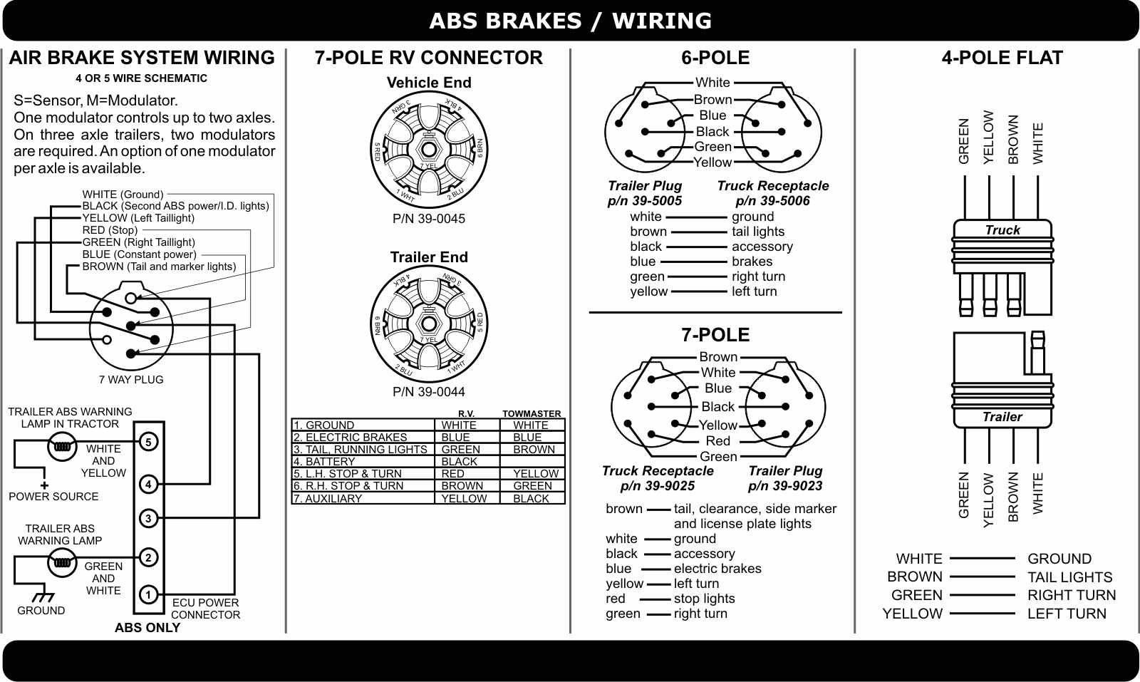
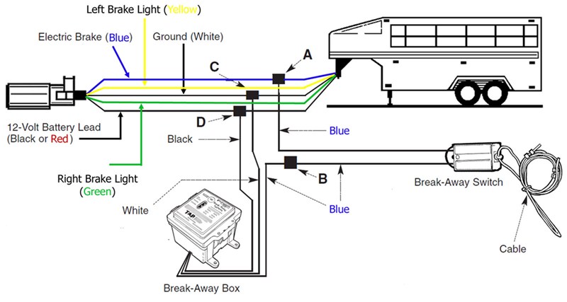
The white wire is the ground or negative wire connecting to the vehicle battery minus side. Each component ought to be set and connected with different parts in particular manner. It reveals the parts of the circuit as streamlined forms as well as the power and signal connections in between the gadgets. Assortment of electric trailer brake wiring schematic. This e book even consists of recommendations for additional provides that you might need to be able to complete your assignments. Wiring a 7 pin trailer plug australia today wiring diagram 7 pin trailer wiring diagram with brakes.
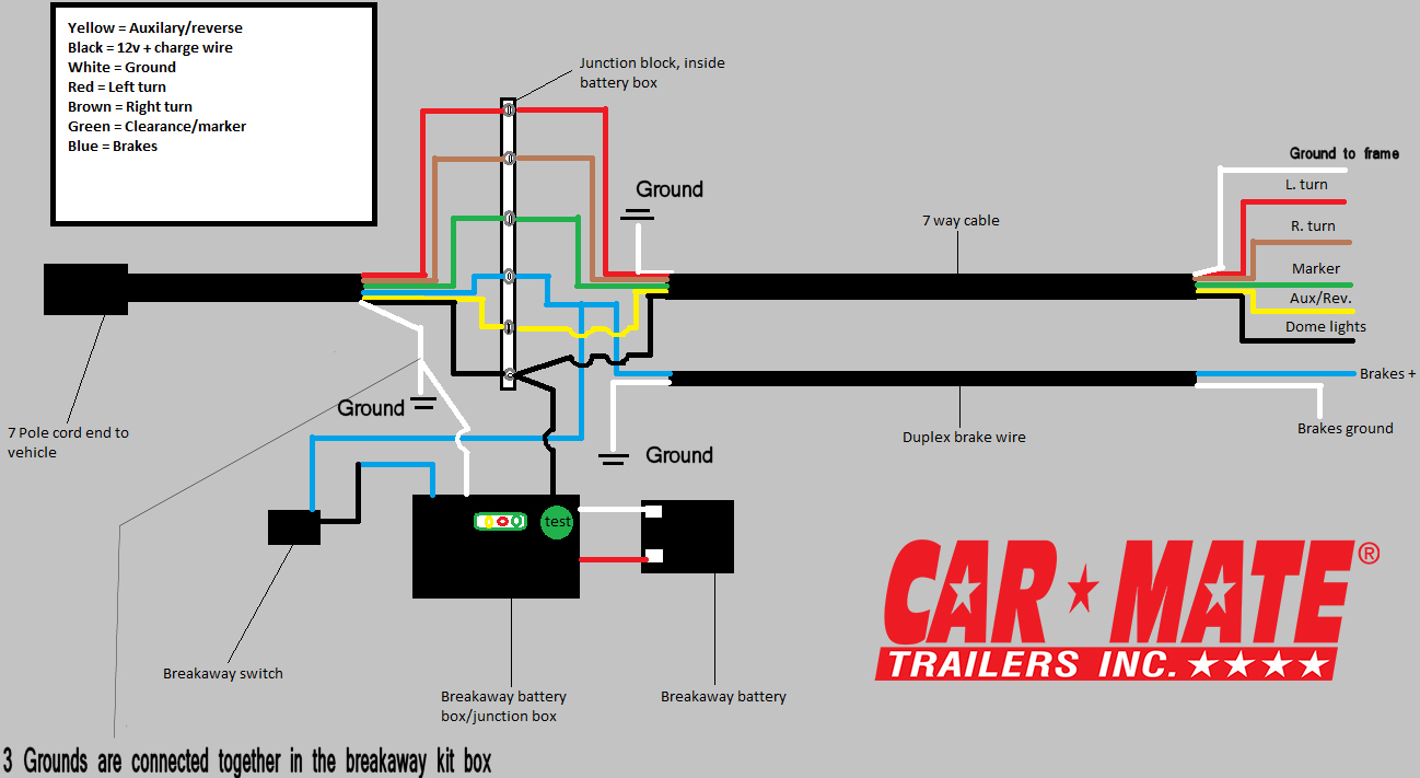
This car is designed not just to travel one place to another but also to take heavy loads. The battery is equipped with four 516 inch holes but it is only necessary to use two of them. The four wires control the turn signals brake lights and taillights or running lights. If the trailer has an on board battery skip. 4 way trailer connectors are. You will need to wire it in between the breakaway battery and the tilt battery and it will stop the backfeeding from your tilt battery to the rest of the 12 volt circuit wiring of your trailer.
The trailer wiring diagram shows this wire going to all the lights and brakes. Also it must connect with things if included that use the aux power and back up lights too. 7 pin trailer wiring diagram with brakes 7 pin flat trailer wiring diagram with brakes 7 pin rv trailer wiring diagram with brakes 7 pin trailer wiring diagram with brakes every electrical arrangement is made up of various different parts. Various connectors are available from four to seven pins that allow for the transfer of power for the lighting as well as auxiliary functions such as an electric trailer brake controller backup lights or a 12v power supply for a winch or interior trailer lights. Check out the diagram i put together to show you how it should all get wired up. They also provide a wire for a ground connection.
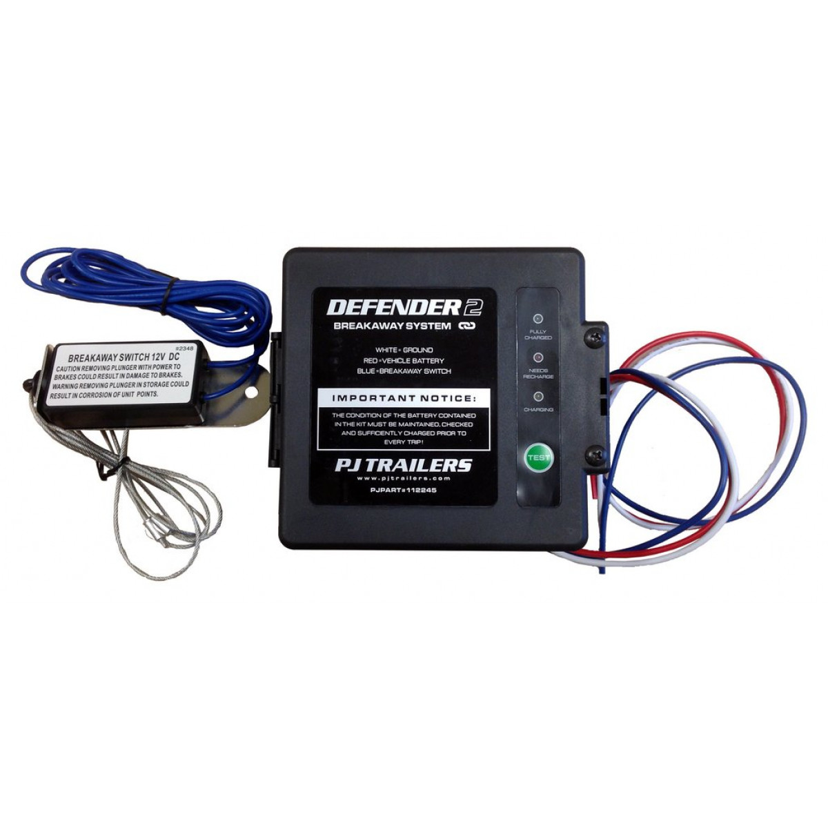
Position the box and mark the holes then remove the box and drill the holes. Trailer breakaway wiring diagram 3 wire trailer breakaway switch wiring diagram hopkins trailer breakaway wiring diagram rv trailer breakaway switch wiring diagram people today understand that trailer is a vehicle comprised of quite complicated mechanics. As the name implies they use four wires to carry out the vital lighting functions.
