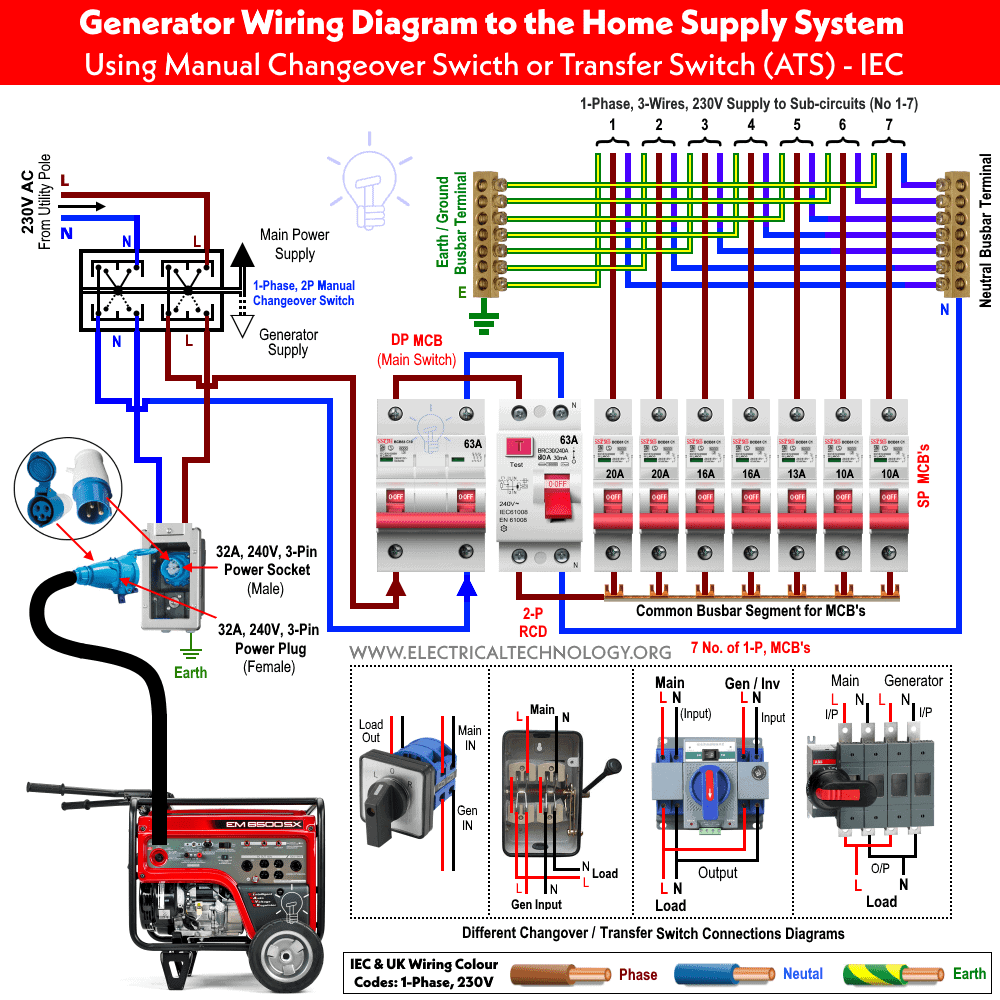
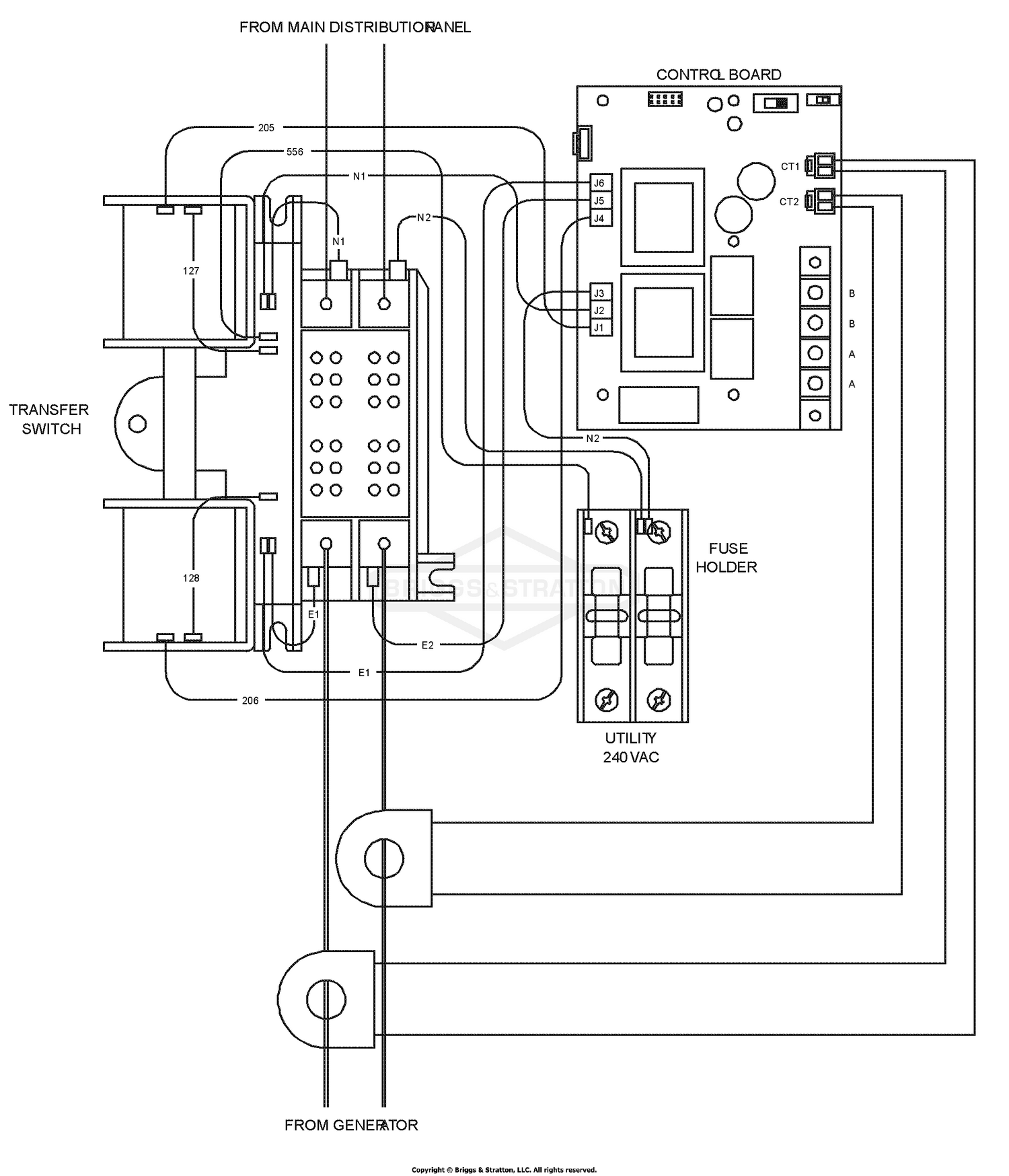
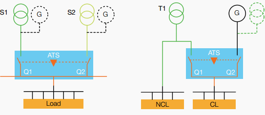
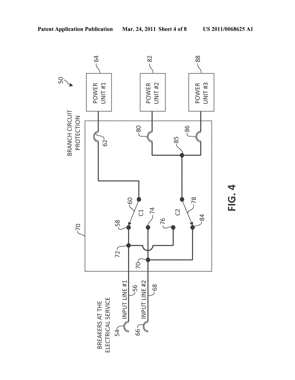
Assortment of manual transfer switch wiring diagram. If utility power fails the switch connects the generators power to the circuits in the generator sub panel.
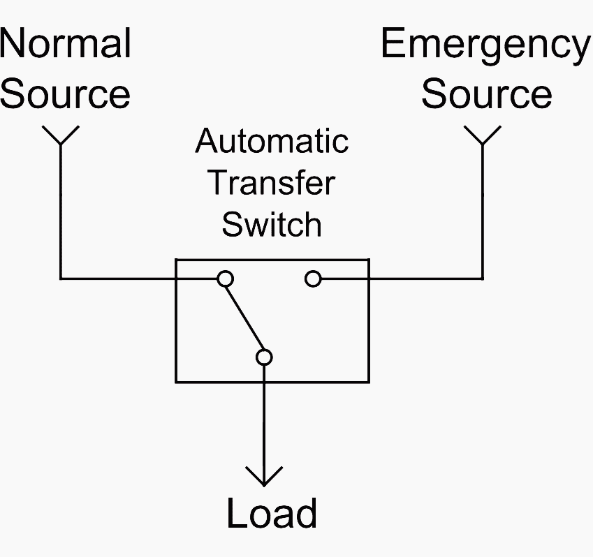
Single Line Diagrams Of Emergency And Standby Power Systems
Transfer switch diagram. Set your store to see local availability add to cart. Screw the receptacle to the box. By design it is a physical impossibility for both power sources to supply the load simultaneously unless of course that is the intent. Variety of reliance transfer switch wiring diagram. Figure 5 wiring diagram of a manual transfer switch in the on position. Lift the transfer switch up to the wall where it is to be installed and label the placement of the mounting screws.
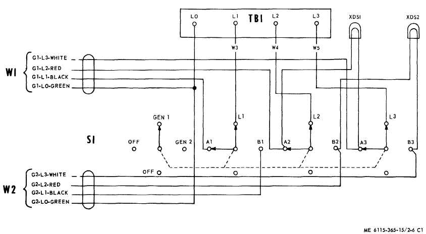
Reliance controls 30 amp 250 volt 7500 watt non fuse 6 circuit transfer switch kit model 3006hdk 279 00 279 00. It shows the components of the circuit as simplified shapes and also the power and also signal links in between the tools. The basic 3 way switch wiring diagram wiring a switched outlet wiring diagram this entry was posted in outdoor wiring diagrams and tagged backup generator do it yourself emergency generator generator transfer switch wiring wiring diagram. Test your work by first starting up the portable generator. A wiring diagram is a simplified traditional photographic depiction of an electric circuit. In its most basic form a transfer switch for a 120240v single phase service is simply a double pole double throw switch of proper ampere rating with a middle off position fig.
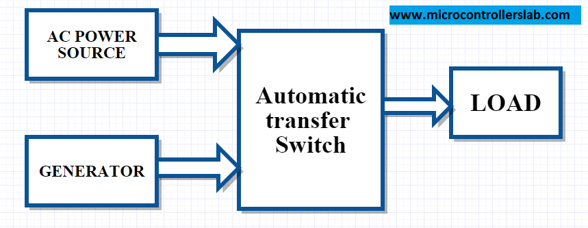
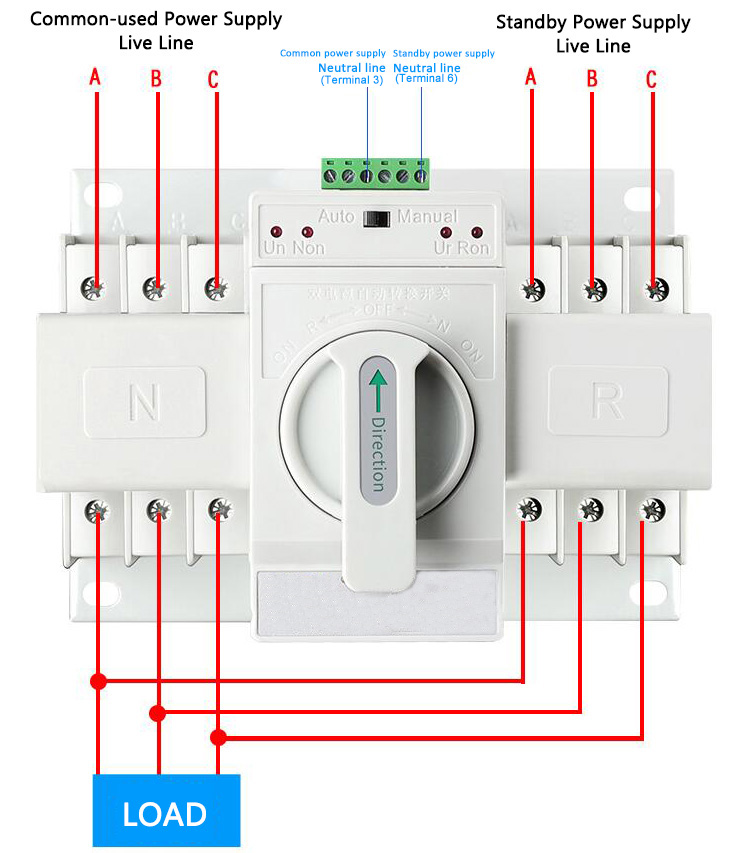
They transfer power automatically to the generator source and switch back to utility power when it is restored. A wiring diagram is a simplified conventional pictorial depiction of an electrical circuit. A wiring diagram is a simplified traditional pictorial representation of an electrical circuit. When utility power is functioning the wires from the circuit breaker in the main electrical distribution panel are connected to the generator sub panel. Run an electrical cable from the box to the transfer switch. Ge 100 amp 240 volt non fused emergency power transfer switch model tc10323r 139 00 139 00.
At the outdoors box connect the cable to the electrical receptacle that comes with the transfer switch. It reveals the elements of the circuit as streamlined shapes and the power and also signal connections in between the gadgets. Move back inside and connect the receptacle cable to the transfer switch. It reveals the components of the circuit as streamlined forms and also the power as well as signal connections in between the gadgets. The transfer switch should be placed roughly 1 12 feet 4572 cm away from the midpoint of the main circuit breaker. A variety of automatic home standby transfer switches are available for use with generac automatic home standby generators.
Collection of residential transfer switch wiring diagram.

