The terms unipolar and bipolar refers to the configuration of the coil winding on each stator within a stepper motor and the type of magnetic field it produces. Stepper motor wiring diagram elegant ponent series circuit diagrams.

Unipolar Stepper Motor Controlling Library Arduino Project Hub
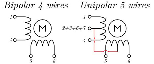
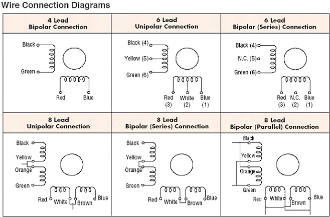
Unipolar stepper motor diagram. Stepper motor wiring diagram sample stepper motor wiring diagram elegant ponent series circuit diagrams. A typical application of stepper motor is in a 3d printer. This image shows different types of unipolar stepper motor and its leads configuration refer datasheet of your stepper motor to know more. You will find two types of popular stepper motor. The unipolar comes with 5 6 and 8 leads and operates one winding with the center tap per phase of input. The popular controlling modes of of the stepper motor are.
Full step and half step. Here the timer ic 555 works as a. This is a datasheet of a nema 17 6 wire which can be connected as bipolar or as unipolar. Stepper motor driver circuit diagram and explanation. Since in this arrangement a magnetic pole can be reversed without switching the direction of current the commutation circuit can be made very simple eg a single transistor for each winding. Stepper motors are used in areas where a specific amount of rotation is required not achievable using ordinary dc motors.
A stepper motor or a step motor is a brushless synchronous motor which divides a full rotation into a number of steps. The full step can be divided into 2 types. Speaking specifically of holding torque the datasheet shows that if you turn the motor on a unipolar driver it loses 30 of the torque. Easy to build cnc mill stepper motor and driver circuits 6 steps. The frequency of clock generation in this case cannot be kept constant so we need to get variable speed for the stepper motor. Each section of windings is switched on for each direction of magnetic field.
This shows that the stepper motor in general starts at a low rpm and the torque decreases as the speed increases. However the coil configuration is the most important difference between the two. There is a. One phase and two phase. Stepper motors work on the principle of electromagnetism. Thus of two motors of identical size the bipolar motor will be able to produce twice as much torque since at any given time the unipolar motor is only using half of its windings.
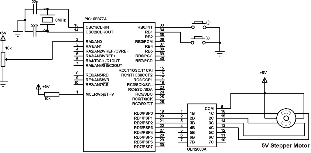
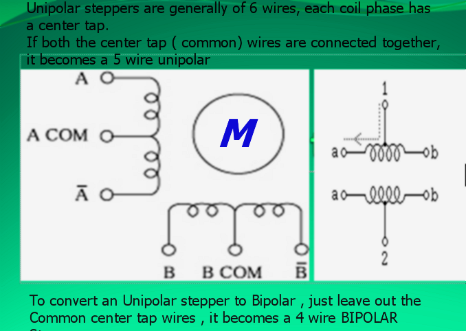
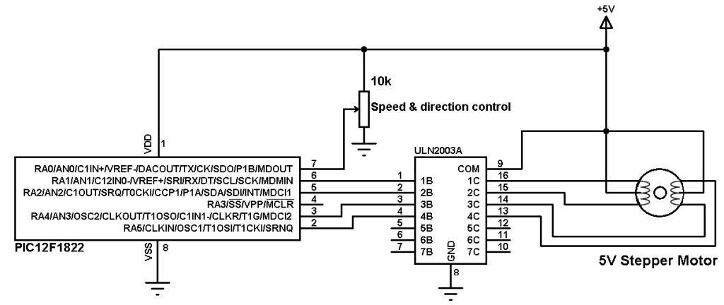
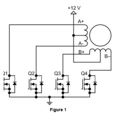
A unipolar stepper motor has one winding with center tap per phase. The other type is the unipolar stepper motor it is 4 phase brushless motor which has 5 or 6 wires. Stepper motor wiring diagram elegant ponent series circuit diagrams. In a bipolar stepper motor each stator coil winding has two terminals however in a unipolar stepper motor each stator coil winding has three. A typical 6 wire stepper motor connection diagram is shown in figure 1. Typically given a phase the center tap of each.
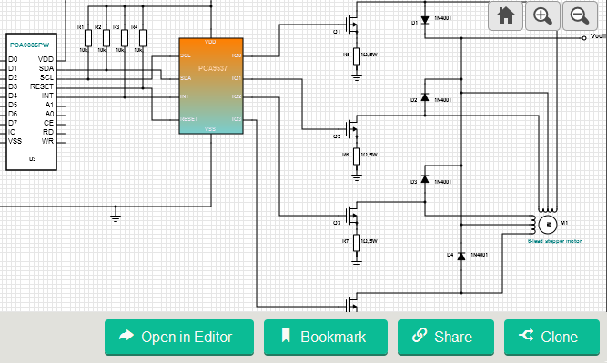
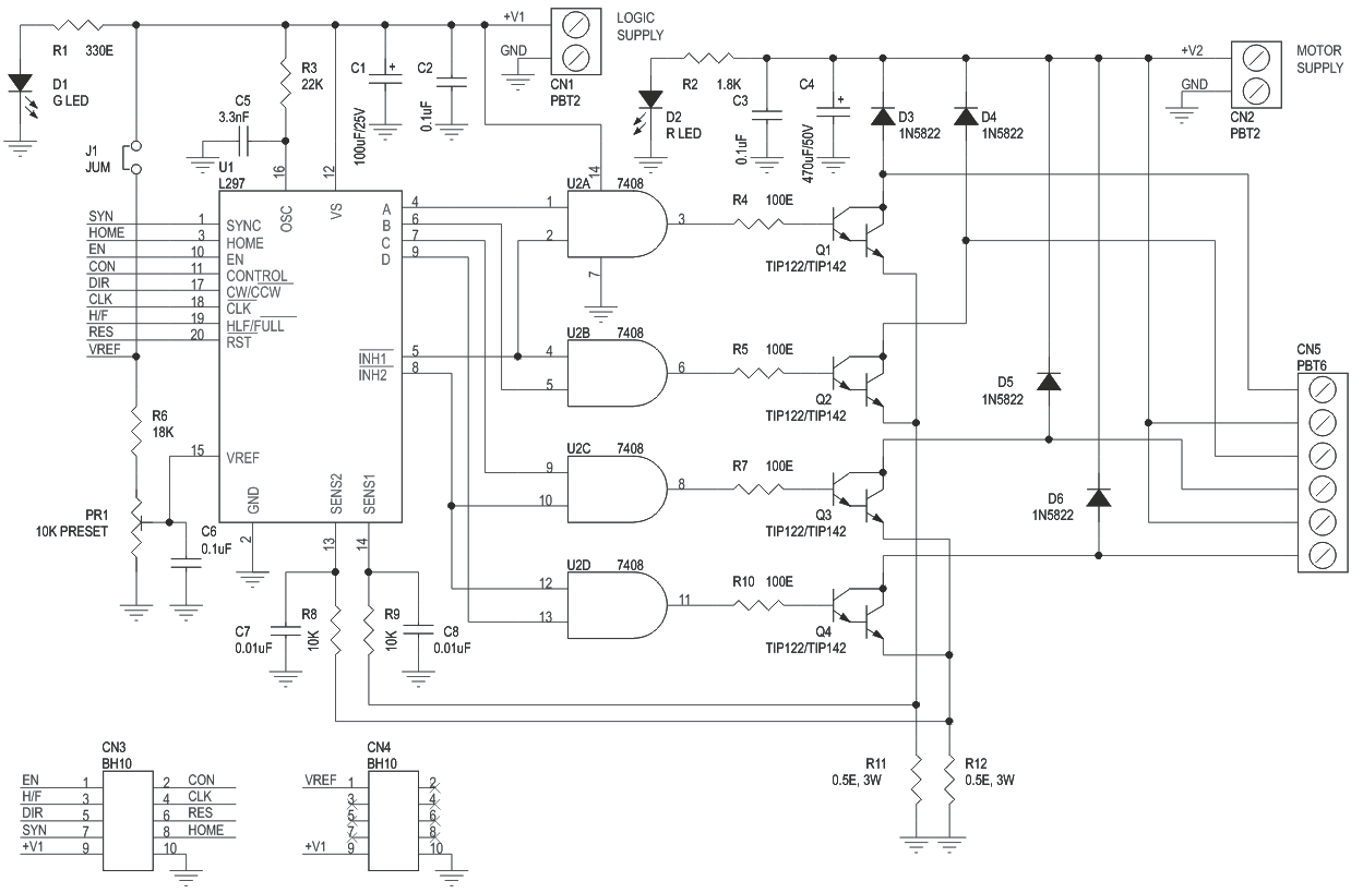
The figure shows the circuit diagram of two stage stepper motor driver. Now as shown in the circuit diagram the 555 circuit here is to generate clock or the square wave. Unlike a brushless dc motor which rotates continuously when a fixed dc voltage is applied to it a step motor rotates in discrete step anglesthe stepper motor can be controlled with or without feedback.
Gallery of Unipolar Stepper Motor Diagram