The lmrc 100 series digital onoff room controllers are the foundation of a wattstopper digital lighting management dlm system and allow integration of occupancy sensors daylighting sensors and switches for energy efficient lighting control. Slide the rubber hinge stopper into the hinge slot as shown to secure the unit.
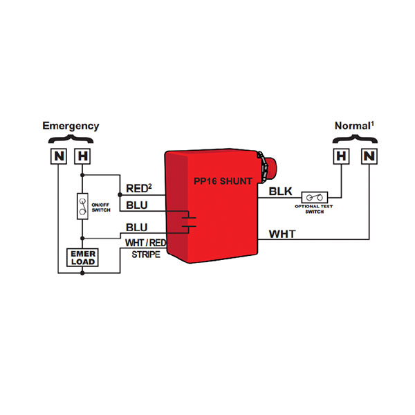
Npp16 D Er Nlight Single Zone 16 Amp 0 10v Dimming
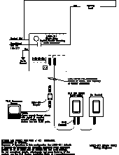
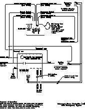
Wattstopper room controller wiring diagram. It measures 44 inch x 32 inch. Line voltage wiring mounting plate tighten. Load ratings include incandescent magnetic low voltage forward phase compatible electronic low voltage and led drivers neon and cold cathode and dimmable two wire and threewire fluorescent ballasts. Wattstopper digital 1 relay room controller has voltage rating of 120277 volt ac at 5060 hz. Room controller overview the room controller includes three relays and up to three 0 10 vdc dimming outputs to control compatible dimmable ballasts. Controls lmrc eliminating wiring errors wattstopper dlm local network parameters lmrc digital onoff volt dimming room controller with 2 relays and 2.
It has plug n go automatic configuration for easy installation and maximum energy efficiency. Terminate wiring according to wiring diagram. In this tutorial you will learn how to install and connect wallstations sliders occupancy sensors and daylight sensors to your room controller. The switching relays and 0 10 vdc outputs are controlled separately allowing flexibility in wiring and control. Lmrc 210 series digital room controllers include one two or three relays to switch a total of 20 amps a high efficiency switching power supply and one 0 10 volt output per relay for control of dimmable loads including electronic ballasts. Lmrc 220 series digital room controllers include one or two outputs to control a total of up to 20 amps.
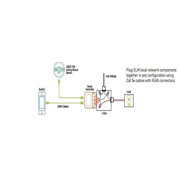
The room controller is shipped preconfigured to work out of the box when connected. Wire connections shall be rated suitable for the wire size lead and building wiring employed. The success of a dlm network installation and the functionality of the segment to this device is followed exactly as depicted in the wiring instructions and diagram. Mounting the controller the room controller mounts to a four square deep junction box using the included mounting plate with the hinge pins extending away from the box as shown. Line voltage room controller deep j box daylight sensor switch dimmer corner mount sensor ceiling.
