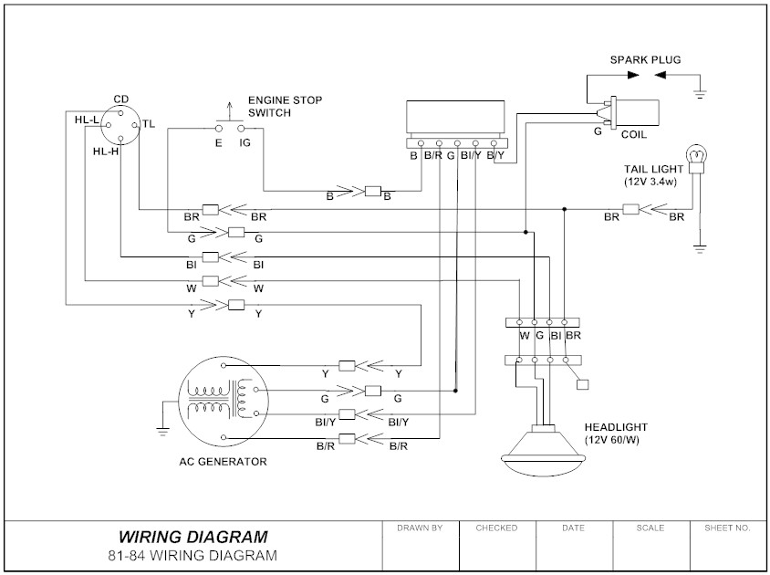
Unlike wiring diagram it does not specify the real location of the components the line between the components does not represent real distance between them. Basics 13 valve limit switch legend.
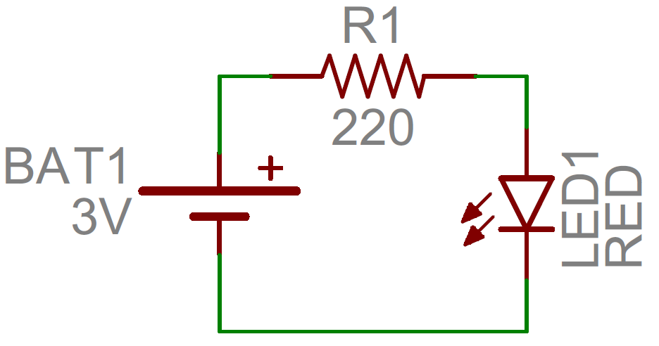
How To Read A Schematic Learn Sparkfun Com
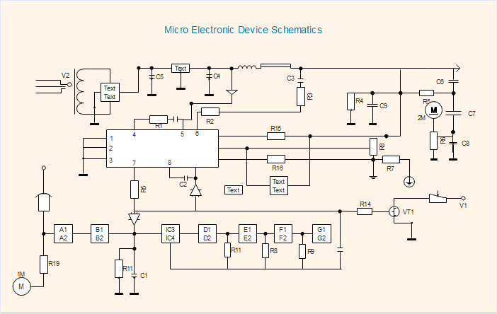
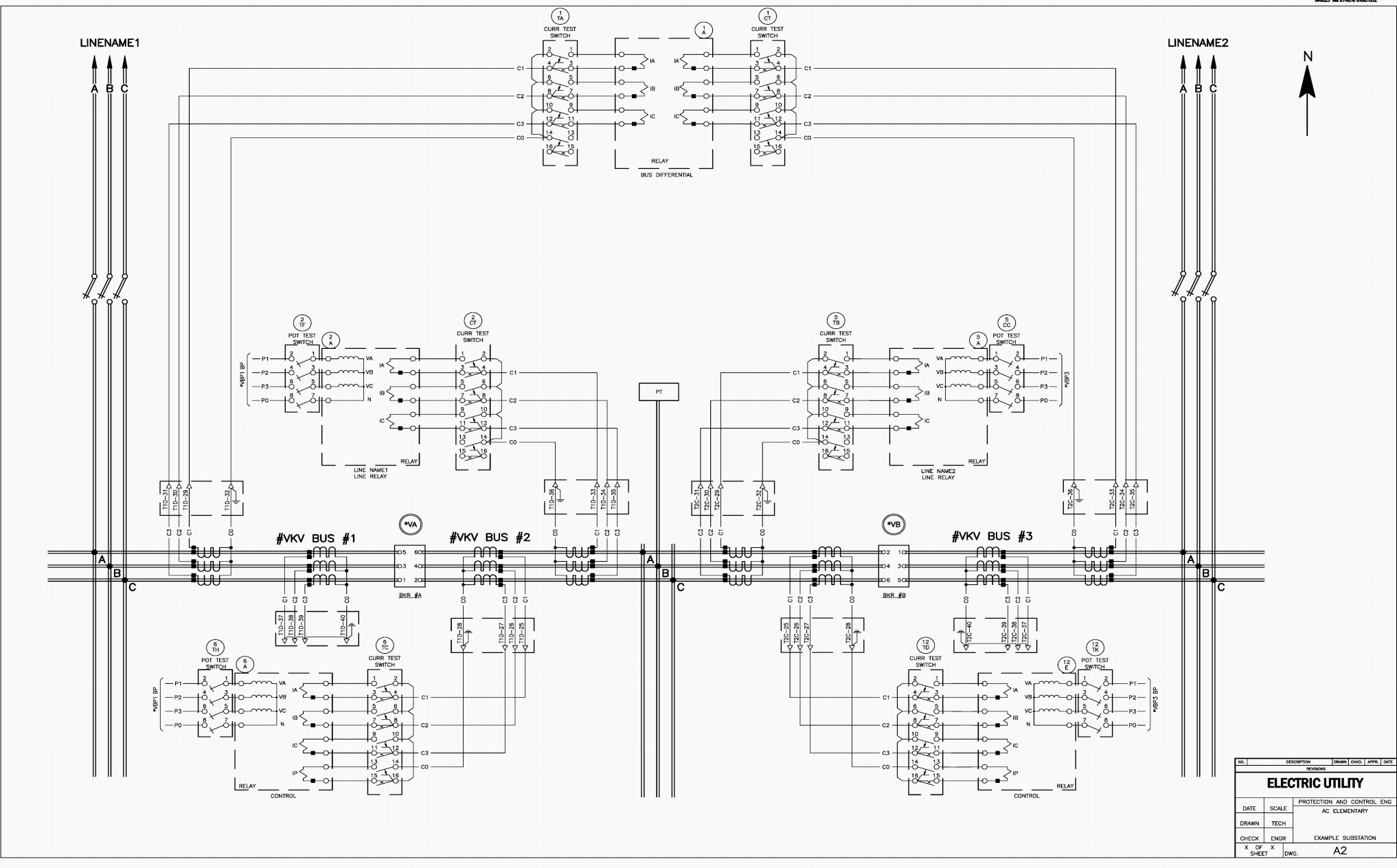
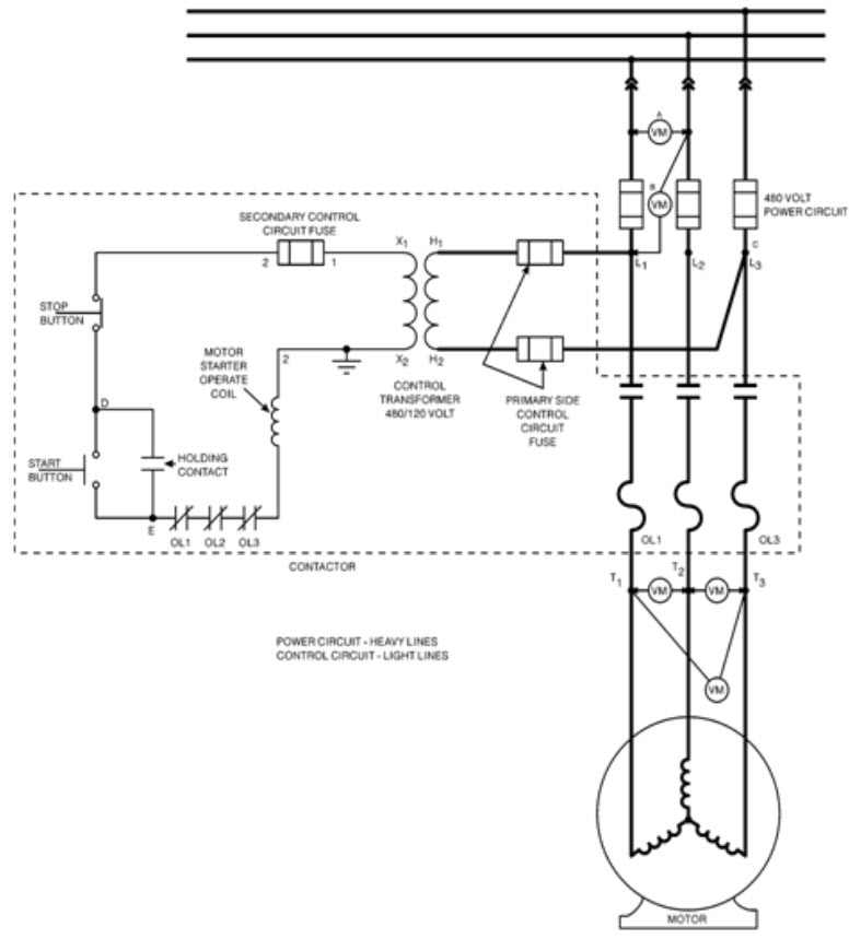
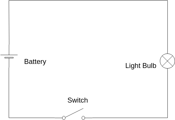
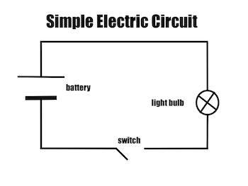
What is schematic diagram in electrical. A schematic diagramis a picture that represents the components of a process device or other object using abstract often standardized symbols and lines. Potentiometers and variable resistors. Schematics are an extremely valuable troubleshooting tool that identify which components are in series or parallel and how they connect to one another. Wiring diagrams show how the wires are connected and where they should located in the actual device as well as the physical connections between all the components. Basics 6 72 kv 3 line diagram. Basics 11 mov schematic with block included basics 12 12 208 vac panel diagram.
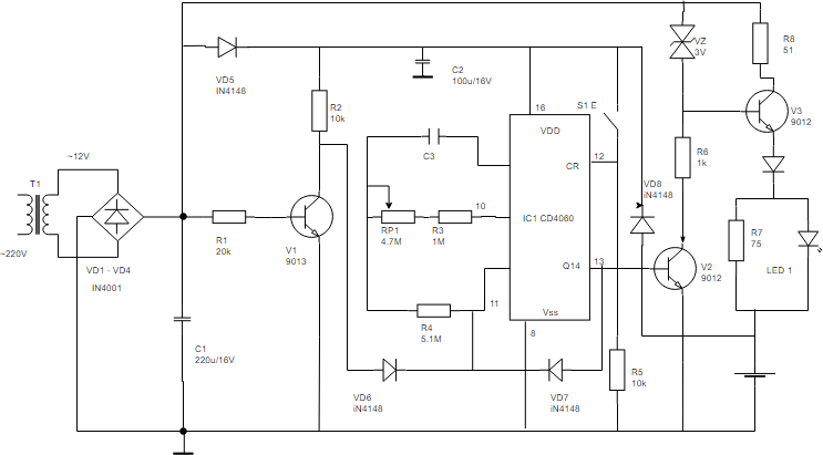
However the pins in the diagram are arranged in a manner that simplifies the connections to be made to the pins. The most fundamental of circuit components and symbols. Although schematic diagrams are commonly associated with electrical circuits many examples can be found in other industries. The 555 has eight pins and the schematic calls for connections on all eight. A versatile cross platform mind mapping tool. The main purpose of a schematic diagram is to emphasize circuit elements and how their functions relate to each other.
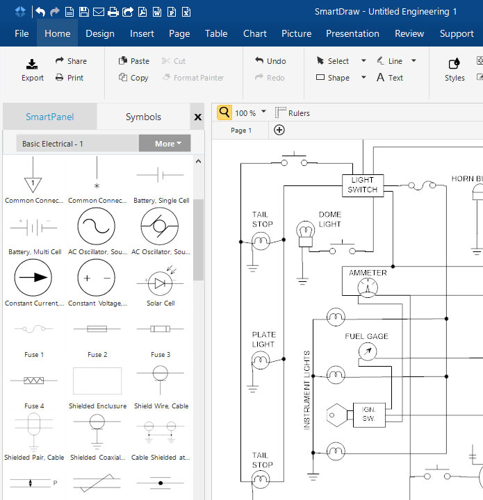
The pins in the diagram are numbered to indicate the correct pin to use. Basics 8 aov elementary block diagram. Basics 9 416 kv pump schematic. An electrical schematic is a logical representation of the physical connections and layout of an electric circuit. The schematic diagram of an electrical circuit shows the complete electrical connections between components using their symbols and lines. These electrical symbols are smart industrial standard and vector based for electrical schematic diagramsthey are used to represent various electrical and electronic devices or functions.
Resistors on a schematic are usually represented by a few zig zag lines with two terminals extending outward. Electrical switch diagrams that are in color have an advantage over ones that are black and white only. A well documented schematic outlines the functionality of an electric circuit and provides the basis for assembly and troubleshooting of a system. Basics 14 aov schematic with block included. Basics 7 416 kv 3 line diagram. Schematics using international symbols may instead use a featureless rectangle instead of the squiggles.
The individual wires on the diagram should be colored the same as the actual wires you will be using. Schematic diagrams can also differ in their level of abstraction. Basics 10 480 v pump schematic. A popular ic called a 555 timer ic is used to make an led flash. A schematic shows the plan and function for an electrical circuit but is not concerned with the physical layout of the wires.


