Why 3 phase ac instead of single phase. These lines far exceed the 120 volts ac standard in most homes.
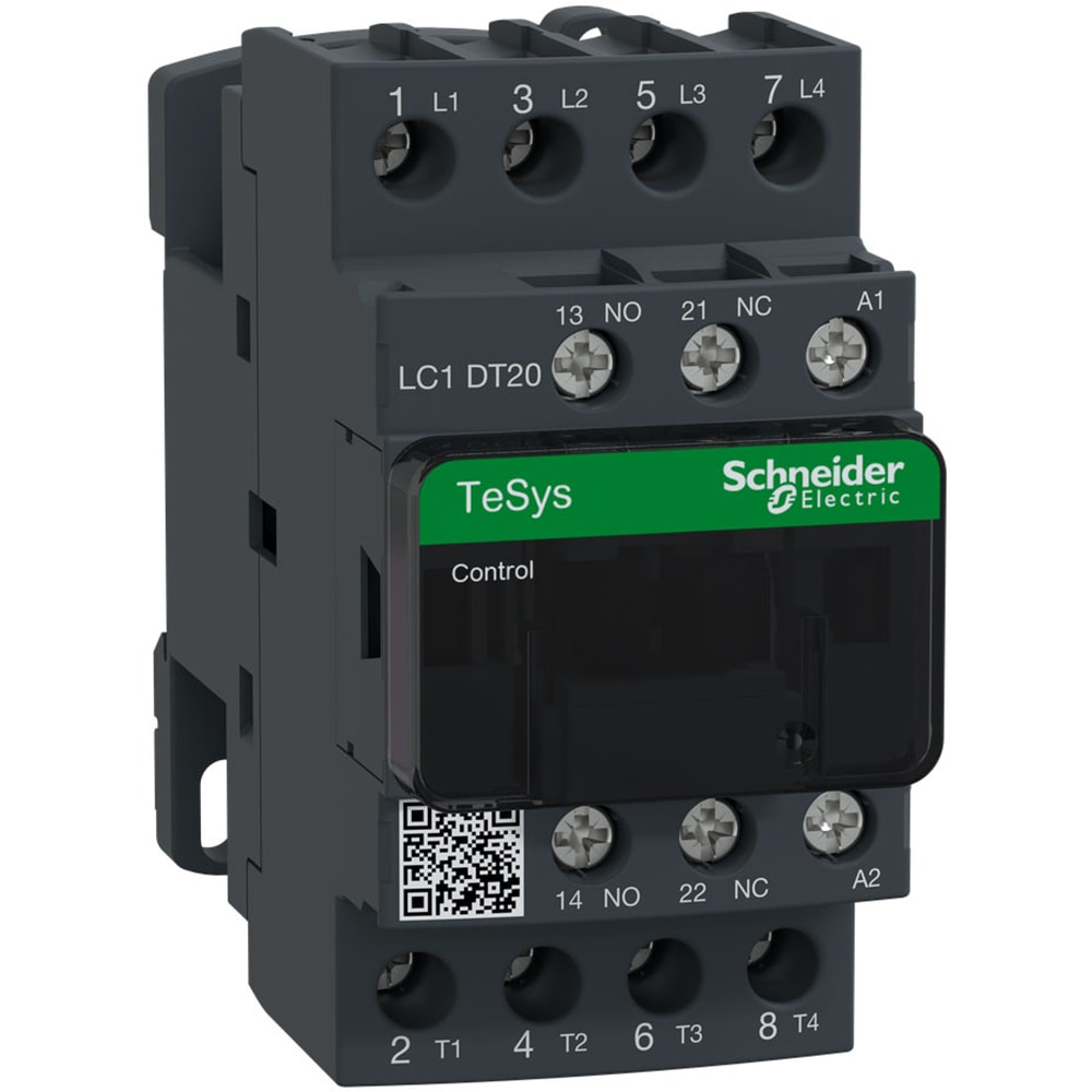
Lc1dt20u7
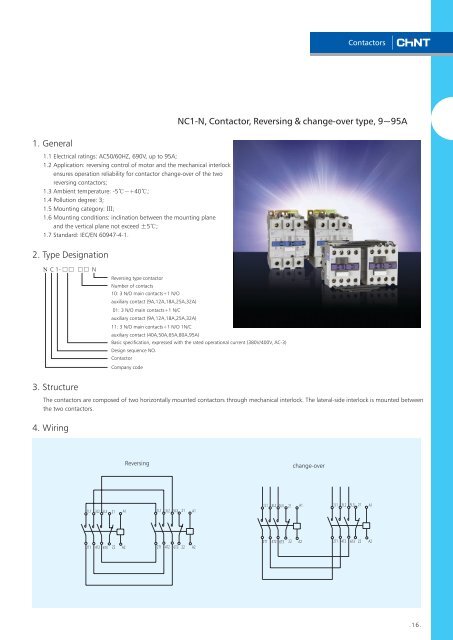
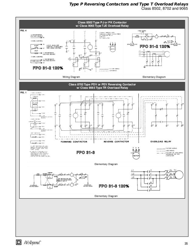
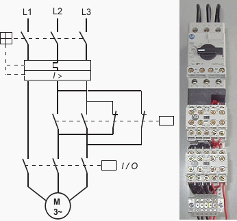
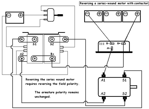
Wiring a reversing contactor. A 3 phase standard non reversing contactor wiring diagram is shown below and has been called relay. Variety of single phase motor wiring diagram forward reverse. Other brands of contactors may be wired the same or similarly. 800 x 600 px source. The schematic wiring diagram of a reversing 3 phase contactor assembly is above. Reversing contactor white rogers 586 diagram for series motors reversing contactor white rogers 586 diagram for series motorspdf.
Winch motor with dc88 reversing contactor. There are four basic wiring combinations. And from the mccb breaker i connect the supply to both magnetic contactors. Here i showed the forward reverse wiring diagram. In the above one phase motor wiring i first connect a 2 pole circuit breaker and after that i connect the supply to motor starter and then i do cont actor coil wiring with normally close push button switch and normally open push button switch and in last i do connection between capacitor. Many large pieces of equipment are powered directly from high voltage lines.
A full voltage non reversing 3 phase motors. How to wire a contactor. 800 x 600 px source. Dissected and explained youtube size. A wiring diagram is a simplified conventional pictorial representation of an electrical circuit. The contactor control voltages may be mains voltage or a special control voltage often 24v dc is used as a standard voltage for control systems in industrial.
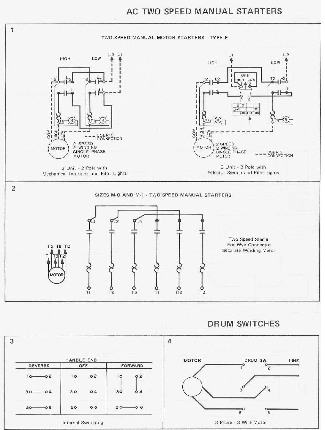
It reveals the components of the circuit as simplified forms as well as the power as well as signal links in between the tools. Consult the manufacturers wiring diagrams for other brands of contactors. Single phase reversing contactor wiring diagram. This article shows how to wire various motors using the fuji series of contactors sold by automationdirect. Alltrax axe reverse with plug brake wire diagram doc100 048 bdwg axe plugbrk rev wire diapdf. In the diagram i connect the incoming three phase supply l1 l2 l3 to the mccb circuit breaker molded case circuit breaker.
Here the l1 is connecting to the both contactors first terminal. L2 wire connected to the. Reversing contactor diagram for permanent magnet pm motorspdf. 240 volts ac and 480 volts ac are commonly used for these large pieces of.

