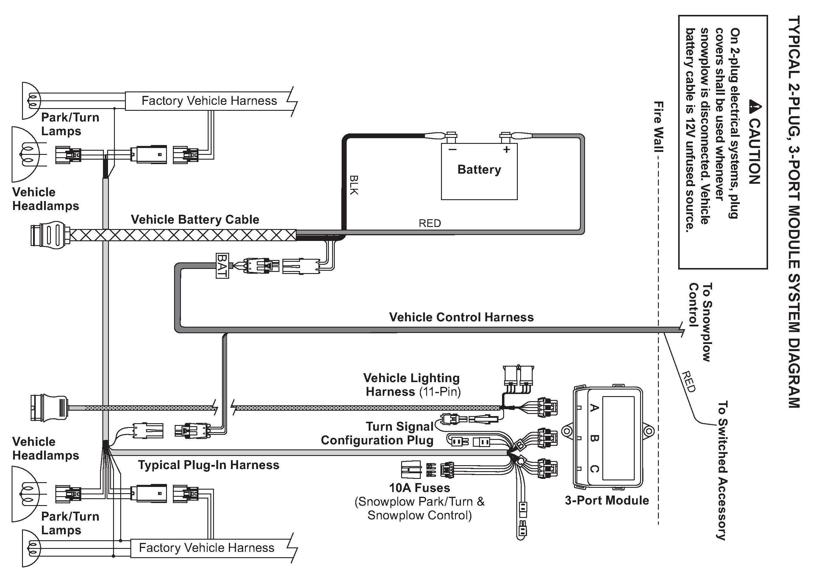
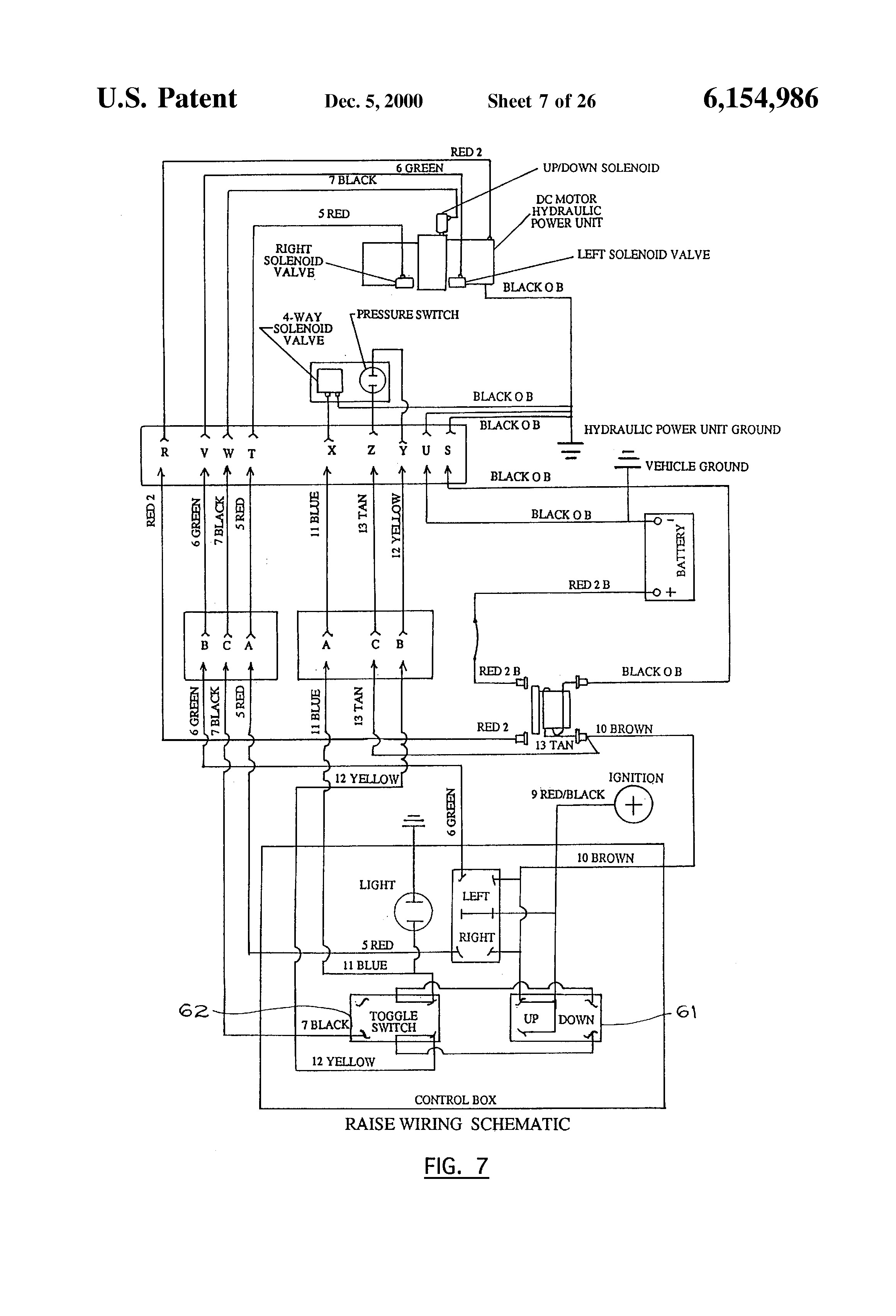
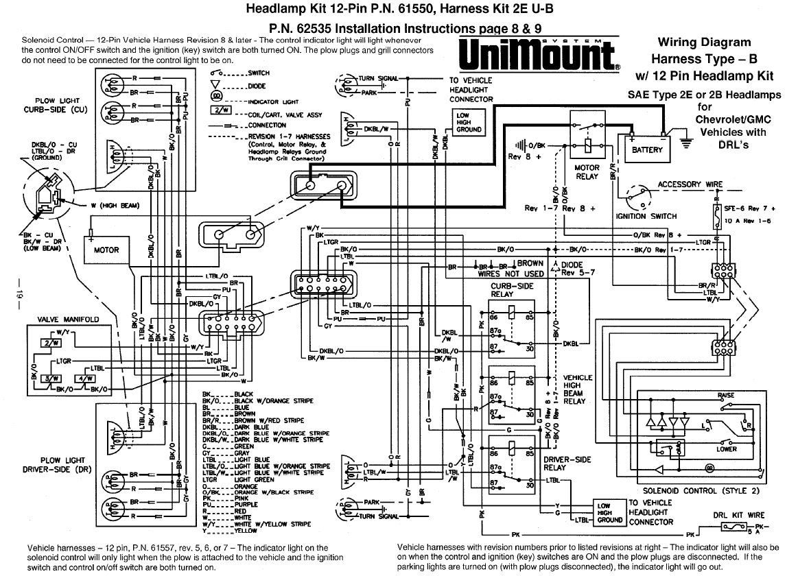
A wiring diagram is a streamlined standard pictorial representation of an electrical circuit. We need a whole new concept for it then one of them is this western unimount light wiring diagram.

Western Snow Plow Ultramount Wide Out Hydraulic Unit Parts
Wiring diagram for a western unimount plow. Western unimount wiring diagram western unimount controller wiring diagram western unimount solenoid wiring diagram western unimount wiring diagram every electrical arrangement consists of various diverse pieces. If not the structure will not work as it ought to be. It shows the components of the circuit as streamlined forms and the power and signal links in between the gadgets. It contains schematics diagrams and charts which supply information for the various types of vehicle and plow headlamp systems. Plow diagrams steel blade frame poly blade frame hydraulic diagrams hydraulic unit hoses angle rams electrical diagrams controllers 2 plug relay system standard headlamps. Western unimount light wiring diagram nov 09 knowledge about western unimount light wiring diagram has been uploaded by brenda botha and tagged in this category.
See coupling lug height check near end of these instructions 2. A new wiring setup for a western unimount without the light wiringif you are hooking up the lights we recommend getting the kit. Assortment of western snowplow wiring diagram. Diagnosis and repair of western snowplow electrical systems. When weight of plow is added. It shows the parts of the circuit as simplified forms as well as the power and also signal links between the tools.
Final coupling lug hole center to level surface distance should be 9 12 to 10 12 with plow attached and resting on the level surface. A wiring diagram is a simplified standard pictorial representation of an electrical circuit. Straight plow standard pro plow. Plow transfer quote request. Assortment of western snow plow wiring diagram. Sometimes we might have to slightly alter the style colour or even equipment.
Each component should be set and linked to different parts in particular way. Attach spreader to mount frame with a 58 x 1 34 bolt and locknut through top hole in spreader angle on each. This is the 9 pin relay style control harness 61437 power harness 61169 power battery cable 22511 and solenoid 56131this gives you the power cable and the control harness but does not have the light harness or the relays. Parts lists installation instructions. Although intended primarily as a diagnostic tool for headlamp systems the hydraulic system circuitry is also included to show the complete electrical system.


%20Schematic%20GG-1%20(edit).jpg)