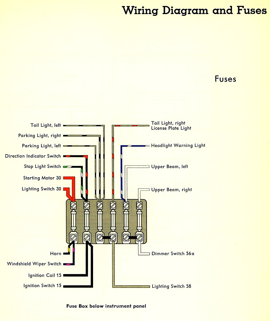
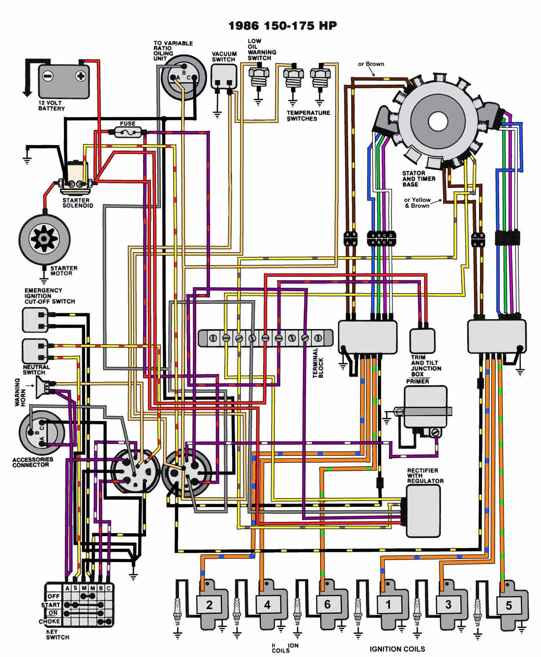
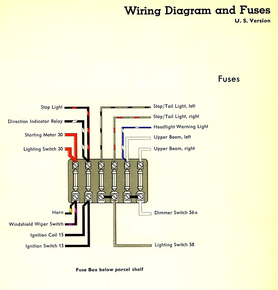
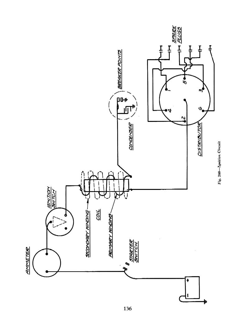
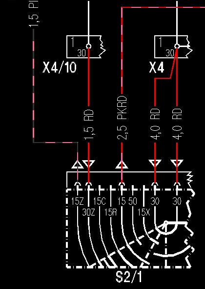
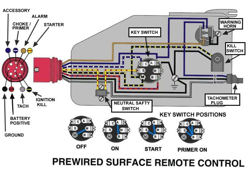
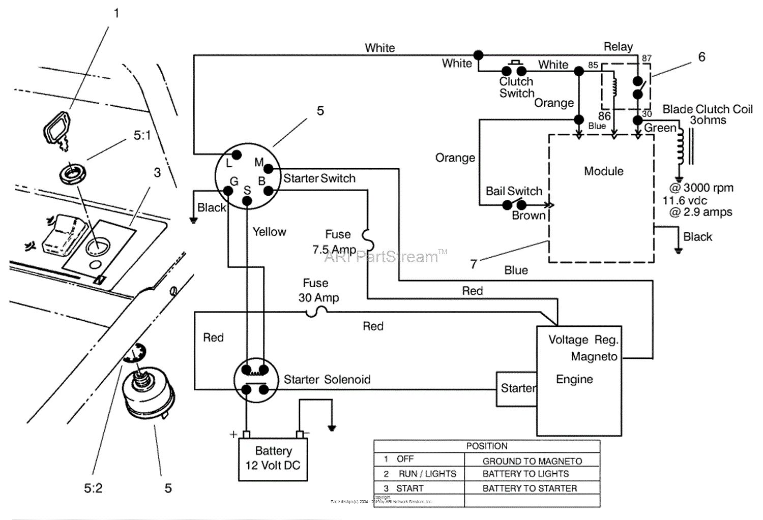
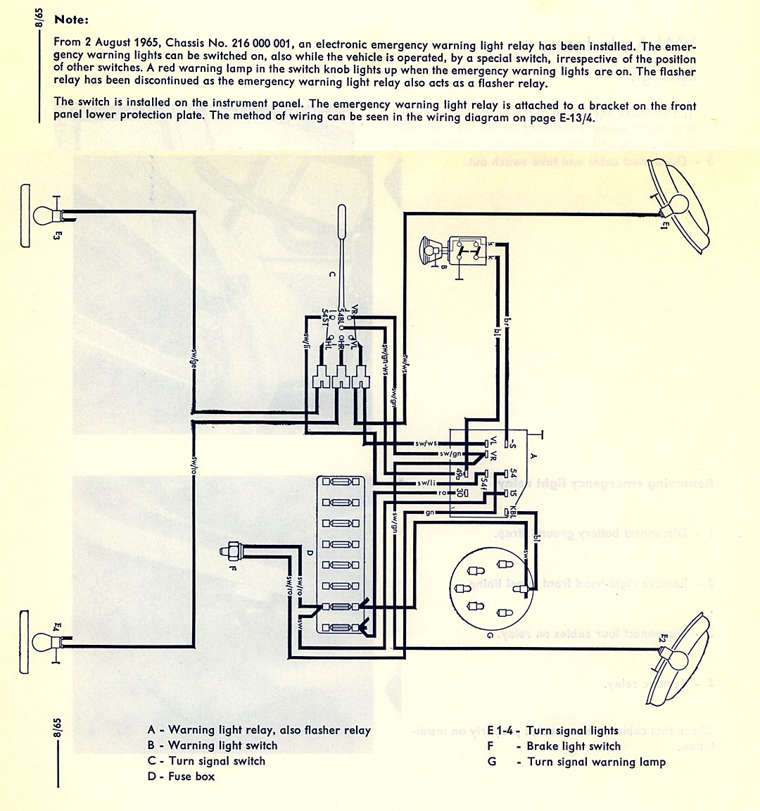
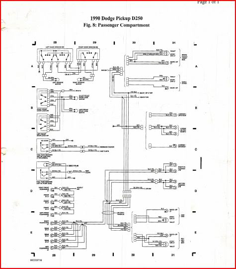
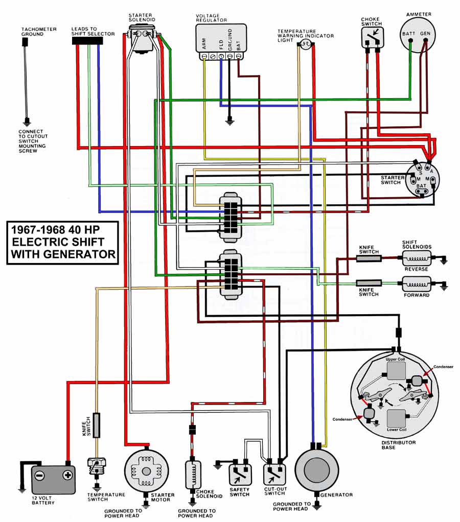
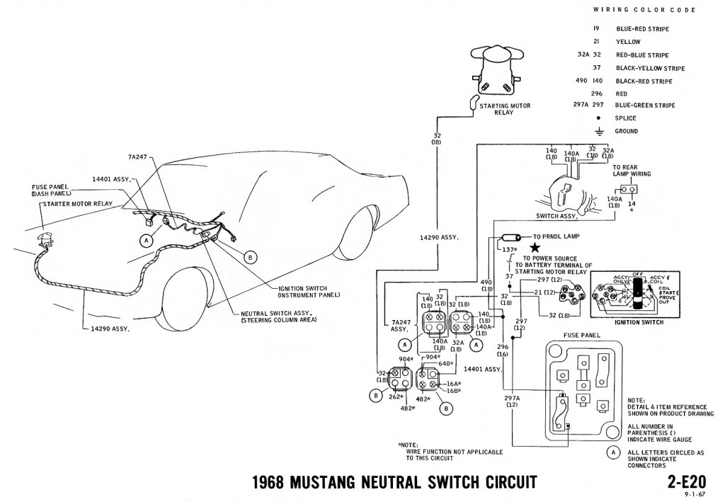
A wiring diagram is a streamlined conventional photographic representation of an electric circuit. The switch positions are acc for accessory r for run s for start and off for off.
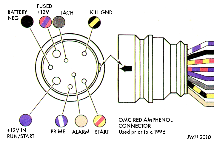
Continuouswave Whaler Reference Ignition Switch
Wiring diagram for ignition switch. This is critical for a successful job. Draw a wiring schematic. The back of the switch is marked with the function of the switch. As a matter of fact a bad diode trio in a conventional alternator can do the same damage. It shows the parts of the circuit as streamlined shapes and the power and also signal links in between the gadgets. It reveals the parts of the circuit as simplified shapes and also the power as well as signal connections between the devices.
Replacement of the ignition switch becomes necessary when. Variety of boat ignition switch wiring diagram. A wiring diagram is a streamlined traditional pictorial representation of an electric circuit. Suzuki outboard ignition switch wiring diagram youll need an extensive expert and easy to know wiring diagram. The main purpose of the switch is to allow the operator to safely engage the ignition system and activate the electric starter. Collection of evinrude ignition switch wiring diagram.
The ignition switch in a motor vehicle is the main electrical component used by the operator to start run and turn off the vehicle. Plan each circuit carefully and include circuit protection either inline fuses or a fuse panel in the diagram. With this sort of an illustrative manual you will have the ability to troubleshoot stop and complete your tasks with ease. The purpose of an ignition ballast resistor between the ignition switch 12v and the ignition coil positive terminal is to restrict current flow.


