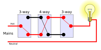
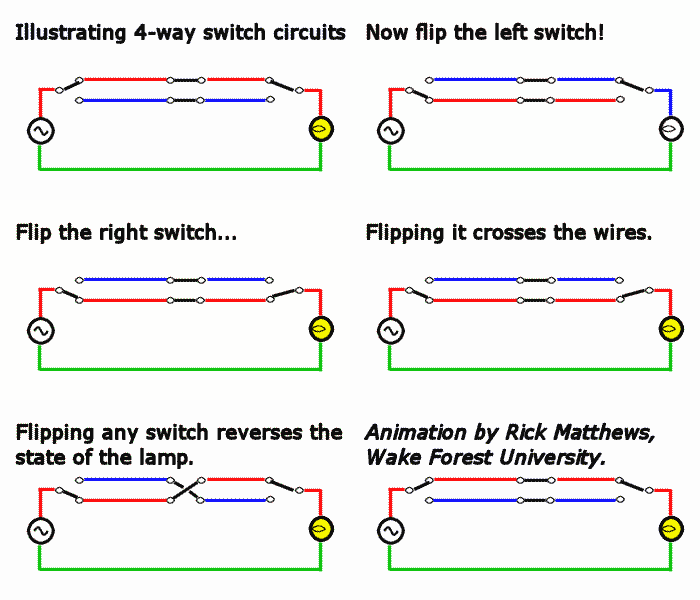
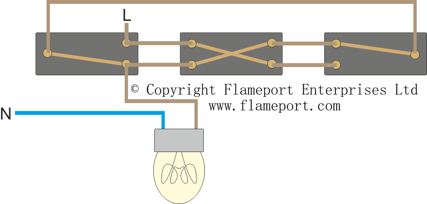
Intermediate switch related circuit diagrams and wiring diagrams intermediate switch wiring diagram old cable colours intermediate switch wiring diagram new cable colours the intermediate light switch is used where three or more switches control one light and used in conjunction with two two way light switches to achieve this. Multiple receptacle outlets can be connected with lighting outlets as depicted in the above light switch wiring diagram.

Wiring Light Switch Or Dimmer
Wiring diagram for intermediate light switch. See the light switch wiring diagrams above and below. The source is at sw1 and 2 wire cable runs from there to the fixtures. You would just continue from one 3 way switch box with the 143 three conductor cable two colored traveler wires a white neutral and a bare or green ground wire in and out of each four way switch box. The hot and neutral terminals on each fixture are spliced with a pigtail to the circuit wires which then continue on to the next light. This allows a single light to be turned on or off from any of the switches. This page shows it wired in the old cable colours if your house has the new colours you want to go here.
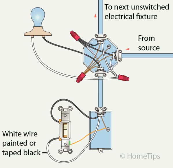
When the switch knob is up the terminal contacts of intermediate switch connect terminal a with terminal c and terminal b with terminal d as shown in fig 1a. The four terminals of intermediate switch construction and its operation are shown in fig below where the 4 contact points may be known as a b c d. Here we have a 3 way switching lighting circuit sometimes called two way switching with intermediate. Light switch wiring diagram with power from the circuit breaker panel going to an electrical receptacle outlet and then continues to the next outlet and then to a single pole wall switch and then to another outlet. In some countries the four way is called an intermediate switch. This diagram illustrates wiring for one switch to control 2 or more lights.


