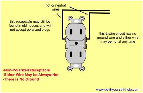
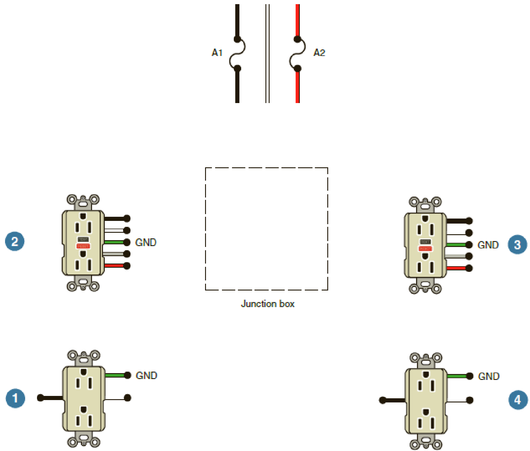
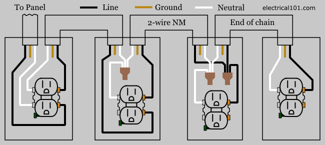
The 15a 125v receptacle is the most widely used device in your home. In the diagram below a 2 wire nm cable supplies line voltage from the electrical panel to the first receptacle outlet box.
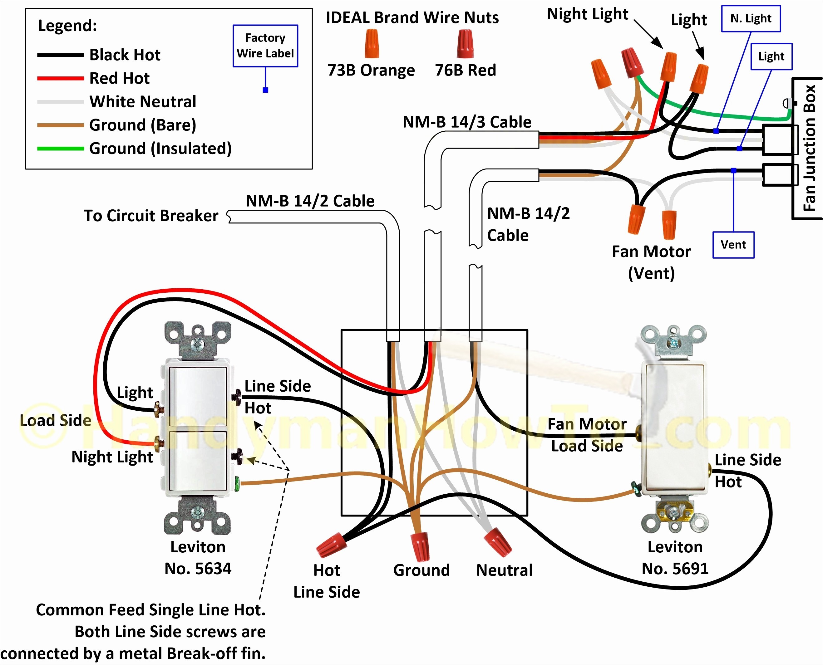
Leviton Gfci Receptacle Wiring Diagram Mycoffeepot Org
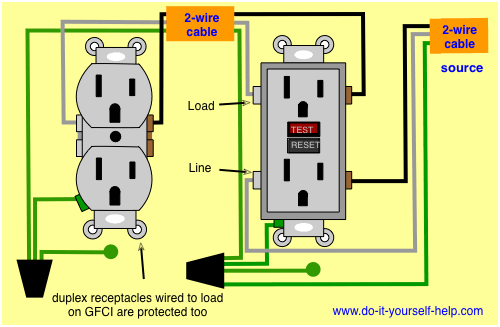
Wiring diagram for receptacle. Wiring diagram for a 20 amp 120 volt duplex receptacle a 20 amp 120v duplex receptacle outlet like this should be installed in a circuit using 12 awg cable and a 20 amp circuit breaker. It means all the connected loads to the load terminals of gfci are protected. Steps to take when wiring the electrical outletreceptacle. These receptacles are usually found in kitchen wall outlets where two branch circuits are needed to serve small appliances and a refrigerator separately. Wiring a gfci outlet with combo switch outlet receptacle light switch. This repeats until the end of the chain.
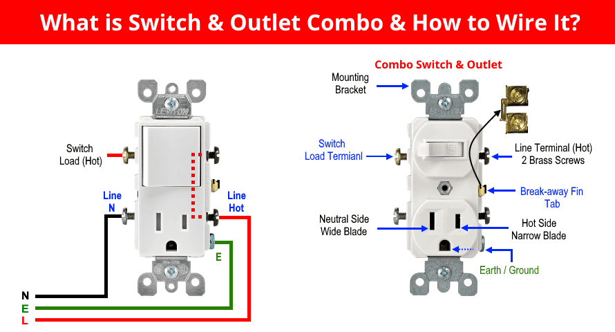
The single pole switch has a neutral conductor for future electronic controls such as a timer or a wifi switch. In this gfci outlet wiring and installation diagram the combo switch outlet spst single way switch and ordinary outlet is connected to the load side of gfci. The black wire line and white neutral connect to the receptacle terminals and another 2 wire nm that travels to the next receptacle. Wiring a receptacle also referred to as an outlet is another of those fundamental wiring skills that every diyer should feel comfortable undertaking. Wiring diagram of a switched electrical receptacle outlet and an unswitched electrical receptacle outlet with the power entering the switched outlet electrical box from the circuit breaker panel. How to wire an electrical outlet wiring diagram wiring an electrical outlet receptacle is quite an easy jobif you are fixing more than one outlet the wiring can be done in parallel or in series.
This article and detailed wiring diagram explains the steps to wiring the common household receptacleoutlet.


