The three phase induction motor is the most widely used electrical motoralmost 80 of the mechanical power used by industries is provided by three phase induction motors because of its simple and rugged construction low cost good operating characteristics the absence of commutator and good speed regulation. Capacitor start capacitor run induction motors are single phase induction motors that have a capacitor in the start winding and in the run winding as shown in figure 12 and 13 wiring diagram.

Ah 2792 Ac Wound Rotor Motor Wiring Diagram Free Picture
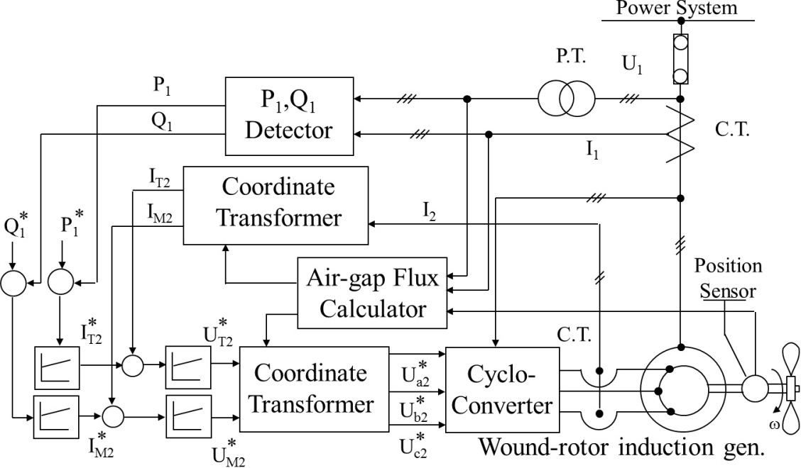
Wound rotor induction motor diagram. 7 however under subsynchronous motor and generator modes all are feasible with adequate control. Wound rotor motors can be started with low inrush current by inserting high resistance into the rotor circuit. This type of motor is designed to provide strong starting torque and strong running for applications such as large water pumps. This article will highlight the important concepts for wound rotor motors that must be understood before purchasing one of these but. This is true for voltage control. There is no electrical connection between these bars.
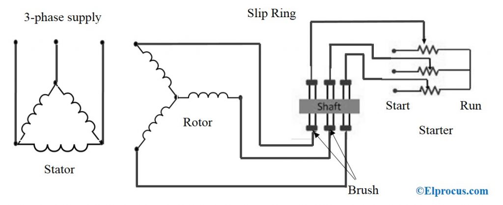
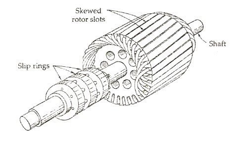
Another type is squirrel cage motor that has no wire winding and has no slip rings. In a squirrel cage induction motor the rotor has conductive bars embedded in slots in the laminations running the length of the rotor. Wound rotor induction motor is used in applications which require smooth start and adjustable speed. Wound rotor induction motor wrim. A wound rotor induction motor has a stator like a squirrel cage induction motor but a rotor with insulated windings brought out via slip rings and brushes. The specifications for a wound rotor motor involves understanding the specifications for all induction motors which can be reviewed in our article all about induction motors.
However no power is applied to the slip rings. Type of induction motor for ac in which the rotor has wire winding. A wound rotor motor also known as slip ring rotor motor is a type of induction motor where the rotor windings are connected through slip rings to external resistance. A different behavior is obtained for constant rotor current control. Three phase wound rotor induction motor. It consists laminated cylindrical core which has a semi closed slot at the outer periphery and carries three phase insulated winding.
Wound rotor motor specifications. Adjusting the resistance allows control of the speedtorque characteristic of the motor. They are used in large pumps in water industry. Example 84 doubly fed im an im with wound rotor has the data. The motor which employing the wound rotor is known as a slip ring induction motor or phase wound motor. The windings are accessible through slip rings.
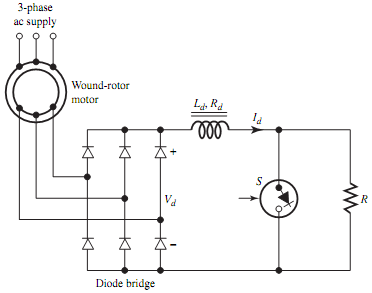
In three phase induction motor the power is transferred from stator to rotor. Some of the applications of this motor include cranes mills hoists and conveyors. Their sole purpose is to allow resistance to be placed in series with the rotor windings while starting figure below. As the motor accelerates. Wound rotor induction motor is also used in fans blowers and mixers. The rotor is wound for the same number of poles as that of the stator.
V sn 220 vphase f 1 50 hz r s. These bars are shorted at each end with shorting rings.
Gallery of Wound Rotor Induction Motor Diagram