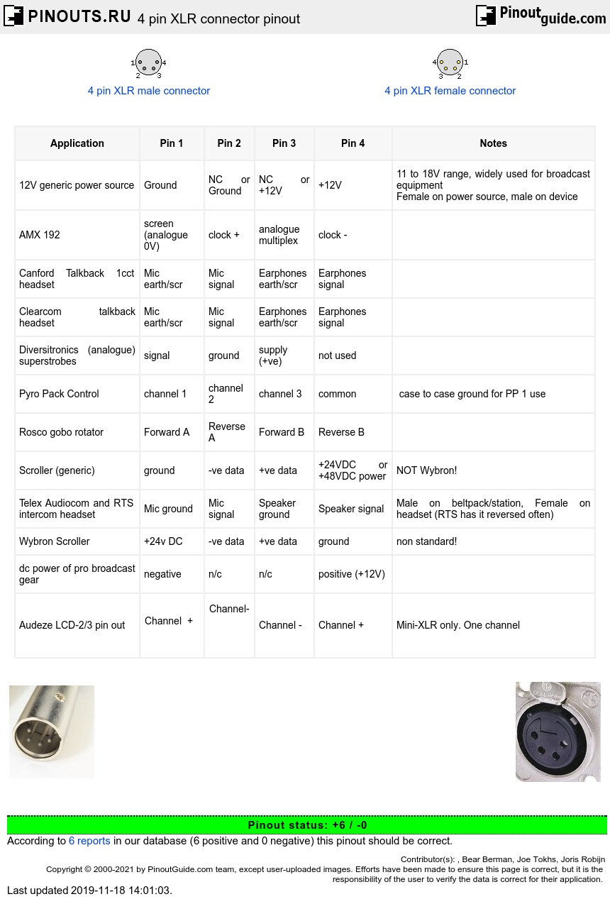
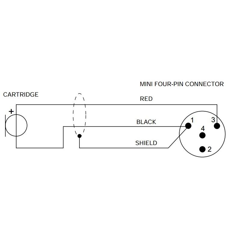
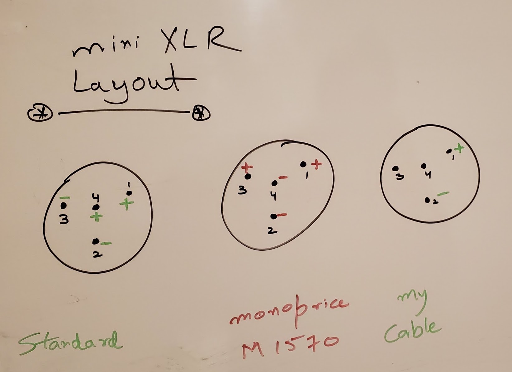
A wiring diagram is a simplified standard photographic depiction of an electric circuit. The above diagram shows you the pin numbering for both male and female xlr connectors from the front and the rear view.

Electrical Cable Socapex Amphenol Wiring Diagram Xlr
Xlr connection diagram. 3 pin xlr wiring diagram cable wiring etc cable designed for being cut into standard mic cables may have 2 pairs of wire and a shield around the outside in that case pair the colors together and make sure they go to the same pin number on each end. 3 pin xlr connectors are standard amongst line level and mic level audio applications. Collection of xlr to mono jack wiring diagram. We hope this. It reveals the components of the circuit as streamlined shapes and the power as well as signal links between the devices. A wiring diagram is a streamlined conventional photographic depiction of an electric circuit.
The surrounding shield should be soldered to pin 1. Xlr to 14 mono plug. An xlr cable is designed to transmit microphone and line level signals over long distances with balanced cables supporting distances over 25 to 30 feet. Preamp tubes improve the sound of any tube guitar amp in an instant. Here is the basic wiring diagram for a standard 3 pin xlr connector used in audio for mics playback machines intercom etc. Collection of xlr wiring diagram pdf.
It shows the elements of the circuit as simplified forms and the power and also signal connections between the tools. The xlr connector is a style of electrical connector primarily found on professional audio video and stage lighting equipmentthe connectors are circular in design and have between three and seven pins. The positive and shield of the xlr are joined together either at the xlr end or the rca end. They are most commonly associated with balanced audio interconnection including aes3 digital audio but are also used for lighting control low voltage power supplies and other applications. The rear view is the end you solder from here are the connections on each pin. Xlr cable 1 jpg xlr wire diagram wiring microphone solutions xlr wiring diagram new clear 3 pin headset audio xlr wiring diagram free diagrams.
Here is a picture gallery about neutrik speakon wiring diagrams complete with the description of the image please find the image you need. They have circular connectors with three pins with one pin for the ground and two for the signal. 3 pin xlr wiring standard. Neutrik xlr wiring diagram on neutrik images. Free download images with neutrik speakon wiring diagrams image size 879 x 675 px and to view image details please click the image. Balanced xlr cables eliminate unwanted noise.
This can be done by either soldering the shield and negative wires of the xlr to the sleeve of the plug. When connecting a 3 pin xlr to one rca you use the same wiring as if you were connecting an xlr to a 14 jack plug. The most comon way to wire a 3 pin xlr to a 14 inch 65mm mono plug sometimes called a jack plug is to join the negative and shield together. Xlr to 1x rca.


