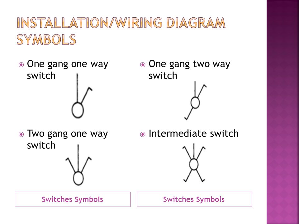
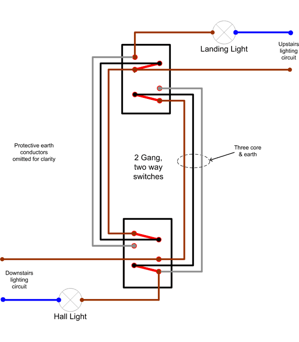
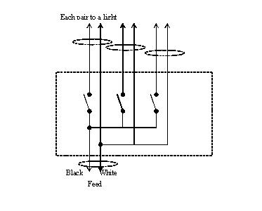
2 gang 2 way switch wiring diagram wiring diagram is a simplified usual pictorial representation of an electrical circuitit shows the components of the circuit as simplified shapes and the power and signal links in the midst of the devices. The red wire from the feed cable is connected to the top terminal the red wire going to.
Wiring Diagram Schneider 3 Gang 2 Way Switch Wiring Diagram
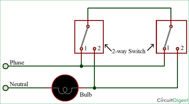
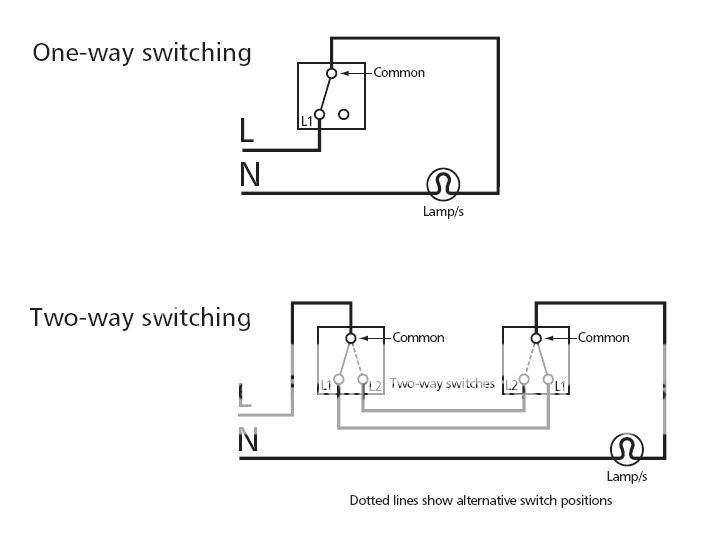
2 gang one way switch wiring diagram. A one way light switch is quite easy to wire up. One way lighting circuit using in line switching. They are wired so that operation of either. This is the first method to make a 2 way switching connection this is the old method. Line diagram of a one way lighting circuit using in line method fig 1. So now that you have a basic concept of wiring a 2 way switch lets look at the following 2 way switch diagrams to see which type of circuit scenario you have.
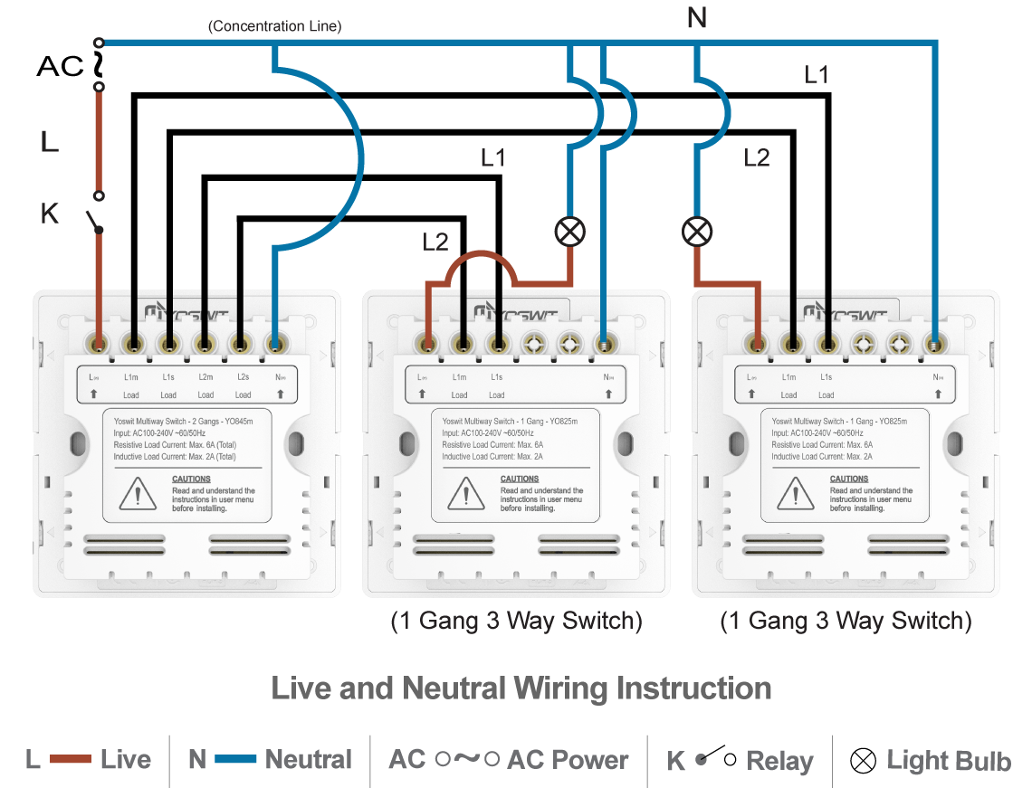
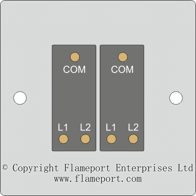
After you have pulled your switch out from the wall the wires in the box and connecting to the switch should look like one of the following. 2 gang 1 way light switch you dont see these as much now days as many manufactures only make 2 gang 2 way light switches that serve the same purpose you just dont use the third l2 terminal on each gang however i thought we would include it just in case you come across one. Wiring a 2gang single switch is a simple and easy way to do. Basic 2 way circuit power coming in at switch. 2 way switch 3 wire system new harmonised cable colours 2 way switching means having two or more switches in different locations to control one lamp. All three way switch and 2 way switch wiring diagrams have the same basic components.
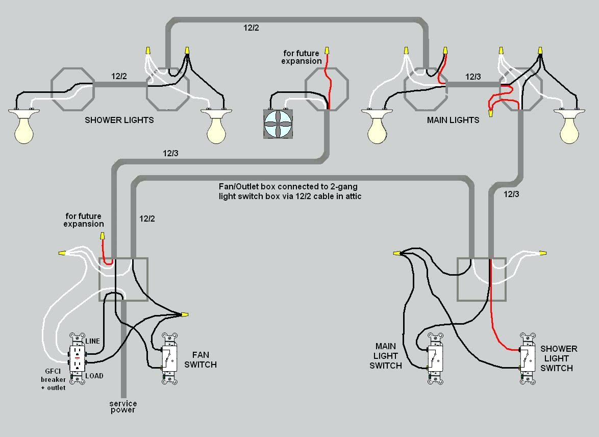
Connecting wires how to connect 2 way switch wiring using two wire control. Wiring two switches in one box with 2 sources. In this video you will be guided from installation to the actual wiring and testing. Wires consisting of a line a load a neutral a pair of travelers and two 3 way switches. Components of 3 way switch wiring. The cable going to the light switch is connected as follows fig 2.
Schematic and actual wiring diagram is also. If you are trying to troubleshoot a 3 way switch operation you will need to identify the function of each wire. If you are going to install a new one then go for three wire control method. This diagram shows two switches in the same box with a separate 120 volt source feeding each. Three wire cable is supplying the source for the switches and the black and red wires are each connected to one switch.
