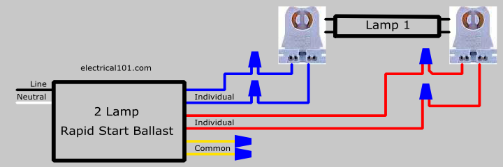
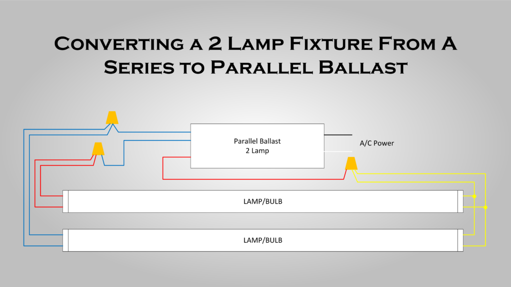
It shows the components of the circuit as streamlined shapes as well as the power and also signal connections between the gadgets. Each component ought to be placed and connected with other parts in specific way.

4120 At Allanson Magnetic Sign Ballast
2 lamp ballast wiring diagram. 2 lamp t12 ballast wiring diagram 2 lamp t12 ballast wiring diagram every electric arrangement consists of various unique pieces. The socket is used with a three way bulb containing 2 separate elements that are energized separately and then together as the switch knob is turned for varying degrees of light. Is this how you have it wired. A wiring diagram is a simplified standard photographic depiction of an electrical circuit. Using two 2 lamp series ballasts. This is a wiring diagram for a standard 3 way lamp switch.
Notice how both the red and blue wires go to one lamp. 4 lamp rapid start two ballasts lampholder wiring diagram. Variety of 2 lamp t12 ballast wiring diagram. It reveals the components of the circuit as streamlined shapes and also the power and also signal connections between the devices. A wiring diagram is a streamlined standard pictorial representation of an electric circuit. 2 lamp blue electronic ballast magnetic ballast universal lighting technologies is a subsidiary of panasonic lighting americas a member of the panasonic corporation eco solutions company 2 lamp rapid start to 2 lamp electronic instant start retrofit wiring diagrams notes.
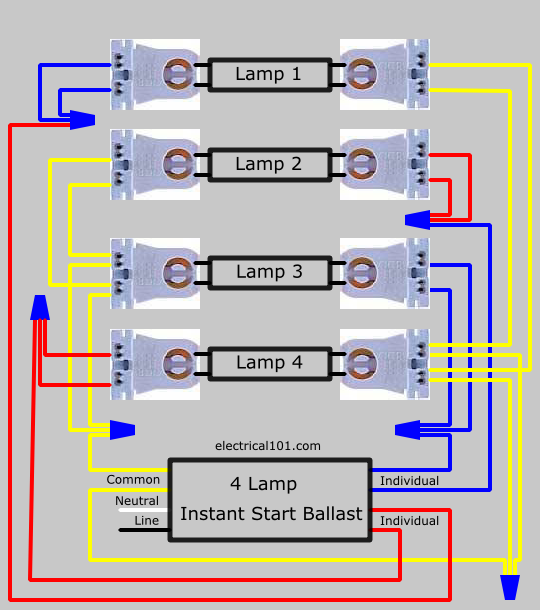
On ballast 2 common wires are connected to the lampholders of lamps 2 and 3 on the left side and the individual wires on the right. This is applicable for 2 lamp t12 rapid start to a 2 lamp electronic. If not the structure will not work as it should be. 2 lamp t8 ballast wiring diagram architectural wiring diagrams reveal the approximate locations and also interconnections of receptacles lights and permanent electrical services in a building. The yellow wires are for lack of a better description are shared so pin 1 of lamp 1 and pin 1 of lamp 2 go one yellow wire. Wiring a 3 way lamp socket switch.
Series ballasts can only be wired in series according to the diagram on the ballast. Pin 2 of lamp 1 and pin 2 of lamp 2 go to the other yellow wire. One 2 lamp ballast usually connects to the two middle lamps the other 2 lamp ballast usually connects to the outer two. If one lamp fails the others can keep operating as the circuit between them and the ballast remains unbroken. These sockets have two terminals one for the hot wire and one for the. Heres a larger view of the wiring diagram.
Variety of 2 lamp t8 ballast wiring diagram. 2 lamp t12 ballast wiring diagram ge 2 ft and 4 t5 120 lamp ballast wiring diagram 6 bjzhjy net rh bjzhjy net t12 magnetic ballast wiring diagram t12 ballast wiring diagram. With some 3 and 4 lamp series parallel ballasts if a single lamp in one branch fails the lamps in the parallel branch will continue to operate.


