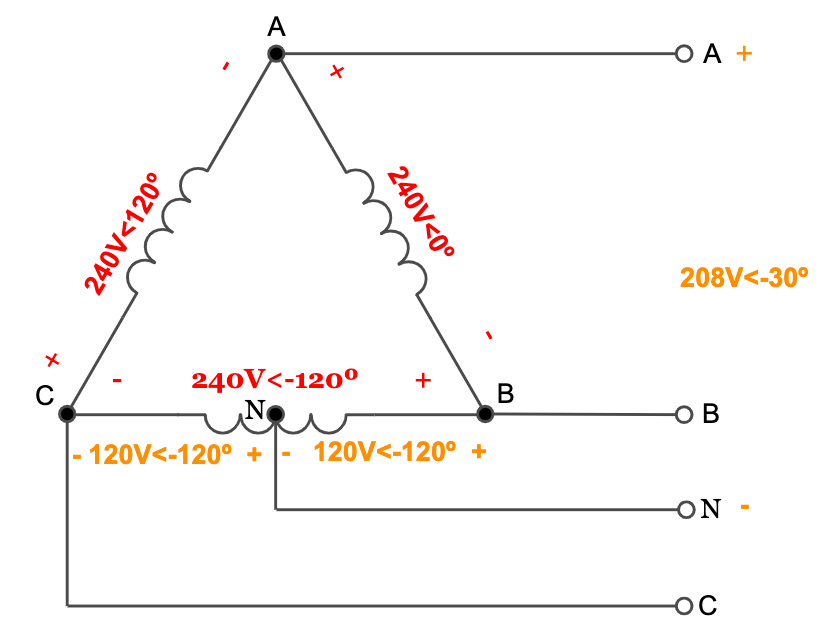
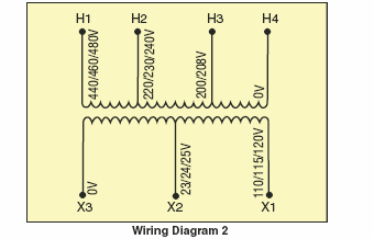
It is intended to help all the average consumer in developing a suitable system. Assortment of 480v to 240v transformer wiring diagram.
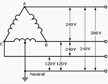
Power Distribution Configurations With Three 3ph Power Lines
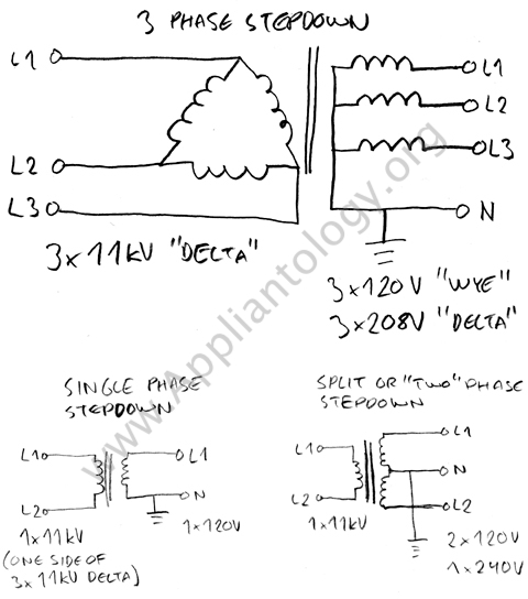
240v transformer wiring diagram. With 120v wiring in the us you have a center tapped transformer with two hots that total 240v. Each component ought to be placed and connected with other parts in particular way. A wiring diagram is a streamlined standard pictorial representation of an electric circuit. The neutral is that center tap which combined with only one of the hots gives you 120v. Transformer wiring diagram 480v to 120 240v wiring diagram 480v to 240v transformer wiring diagram. 240 volt single phase wiring diagram 220 volt single phase motor wiring diagram 220 volt single phase wiring diagram 240 volt single phase motor wiring diagram every electric arrangement is composed of various unique components.
If permitted or required by local code. It shows the parts of the circuit as streamlined forms and also the power as well as signal links between the tools. None x4x1 h4 h3h2 h1 x2 x3 primary. Otherwise the arrangement wont work as it should be. Single phase transformer primary and secondary wiring product line. 3 phase step up transformer 240 to 480 wiring diagram wiring diagram is a simplified pleasing pictorial representation of an electrical circuitit shows the components of the circuit as simplified shapes and the capability and signal contacts in the company of the devices.
Ac current requires a return path electricity goes out one way and back the other. Wiring diagram comes with several easy to follow wiring diagram directions. 480v to 240v transformer wiring diagram 240v to 480v step up transformer wiring diagram 480v 3 phase to 240v single phase transformer wiring diagram 480v to 240v 3 phase transformer wiring diagram every electric arrangement is composed of various unique components. Applies to energy efficient ee type transformers by squaredschneider electric. Collection of 3 phase transformer wiring diagram. It reveals the elements of the circuit as streamlined shapes as well as the power and also signal connections between the gadgets.
Use both of the hots and you have 240v. Each component should be placed and connected with different parts in particular manner. A wiring diagram is a simplified conventional pictorial representation of an electrical circuit. Transformer to wiring imageresizertool com november 23rd to transformer wiring diagram as well asgeneral electrical connection diagramsacme transformer wiring diagrams primary. 12 2 2 anfc 4 2 12 bnfc x4 x1 h10 h2 h3 h1 x2 x3 h5 h6 h4 h7 h8 h9 connect. These guidelines will probably be easy to comprehend and apply.
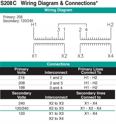
There will be 240v between x1 and x4 with 120v between x1 and the x2x3 junction and 120v between x4 and the x2x3 junction.

